A.2 installation – Comtech EF Data CLO-10 User Manual
Page 88
CLO-10 Link Optimizer
Revision 1
Redundant System Operation
MN/CLO-10.IOM
A.2
Installation
For information pertaining to the CLO-10’s unpacking, inspection, and basic rack mounting instructions,
refer to Chapter 2. INSTALLATION.
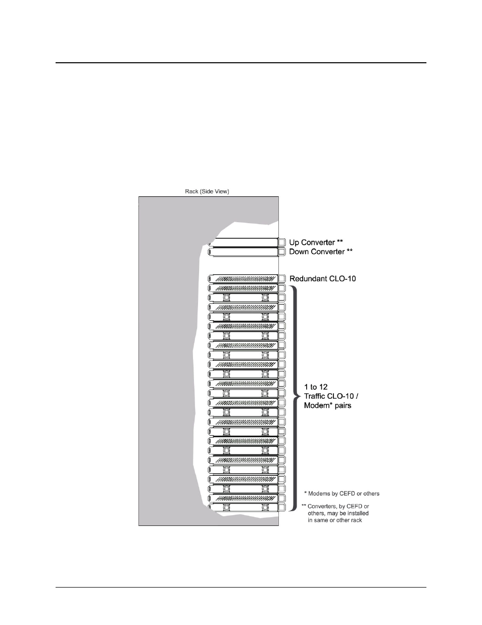
Figure A-3 provides a ‘”cut-away” side view of a typical CLO-10 redundancy configuration; this example
shows up to 12 CLO-10 Traffic Units with one (1) CLO-10 Redundant Unit, for use with any combination of
modems and up and down converters (supplied by CEFD or others).
It is important to ensure that there is adequate clearance for ventilation in the rack. In rack systems where there
is high heat dissipation, provide forced-air cooling by installing top- or bottom-mounted fans or blowers.
Figure A-3. Typical Rack-mounted Redundancy Configuration
A–4