1 led indicators – Comtech EF Data CLO-10 User Manual
Page 58
CLO-10 Link Optimizer
Revision 1
Front Panel Operation
MN/CLO-10.IOM
6.1.1 LED Indicators
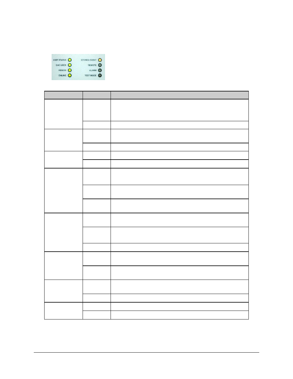
The eight LEDs positioned to the left side of the front panel reflect the
operating condition of the CLO-10 Link Optimizer.
The function of these LEDs is as follows:
LED
Color
Condition
UNIT STATUS
Red
A Unit Fault exists (Unit Fault includes Uplink, Downlink, and
Remod faults).
Example: PSU fault
Green
No Unit Faults exist.
CNC LOCK
Green
CnC has acquired the delay and frequency offset of the uplink
and is suppressing it on the downlink side.
Off
CnC is not locked.
REMOD
Green
The output to the demod (remodulator) is ON.
Off
The remodulation transmitter is currently OFF.
ONLINE
Green
The Unit is Online and carrying traffic. This LED should always
be on in single-thread (non-redundancy) systems.
Green
(flashing)
The Traffic Unit is bridged or in “Hot Standby” – verifies that the
Redundant Unit is configured identically to this unit.
Off
The Unit is Offline (standby) - forced by externally connected
1:1 or 1:N redundancy system.
STORED
EVENT
Orange
There is a Stored Event in the log, which can be viewed from
the front panel or retrieved via the remote control interface.
Orange
(flashing)
CAUTION:
The Redundant Unit is in Manual mode.
Off
There are no Stored Events.
REMOTE
Orange
The Unit is in Remote Mode - Local monitoring is possible, but
Local control is not.
Off
The Unit is in Local Mode - Remote monitoring is possible, but
Remote control Is not.
ALARM
Orange
An Alarm exists (includes Unit, Uplink, Downlink and Remod
Alarms).
Off
No Alarms exist.
TEST MODE
Orange
One of the Test Modes is enabled.
Off
Unit operating in Normal mode.
6–2