6 user data connections – crs-300 to user, Ee figure 4-26, Figure 4-26 – Comtech EF Data CRS-300 User Manual
Page 138
CRS-300 1:10 Redundancy Switch
MN/CRS300.IOM
Cables and Connections
Revision 19
4–64
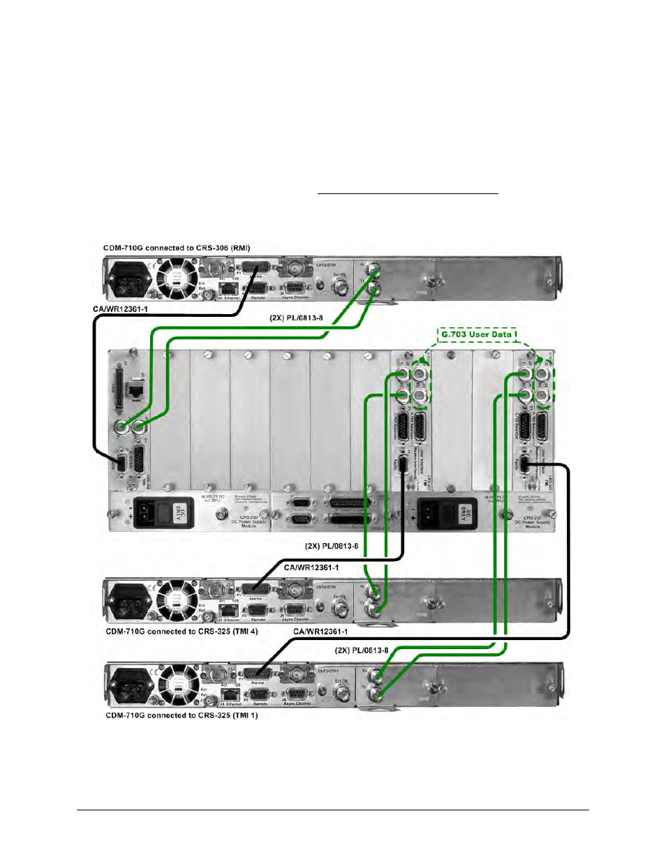
4.8.6 User Data Connections – CRS-300 to User
You must connect your traffic from the external router, multiplexing equipment, or test data
generator to the connectors on the Switch TMI labeled “User Data Interface”. This interface
replaces the direct connection to the Traffic Modem’s “Data Interface” connectors.
Because the Redundant Modem’s function is to replace a faulted Traffic Modem, the Switch RMI
does not have a User Data Interface. See Sect. 1.4.3.3 Modem Interface Cards for detailed
information on the Switch RMI and TMI cards available for use with the CDM-710G/710GL
modems.
Figure 4-26. Control and Data Cables Example #1 – CRS-300 to CDM-710G/710GL
(Connections shown for RMI & TMIs 1 and 3 only)