Table 5-3, D table 5-4 – Comtech EF Data CRS-300 User Manual
Page 178
CRS-300 1:10 Redundancy Switch
MN/CRS300.IOM
Modem, RMI/TMI, and Switch Configuration
Revision 19
5–14
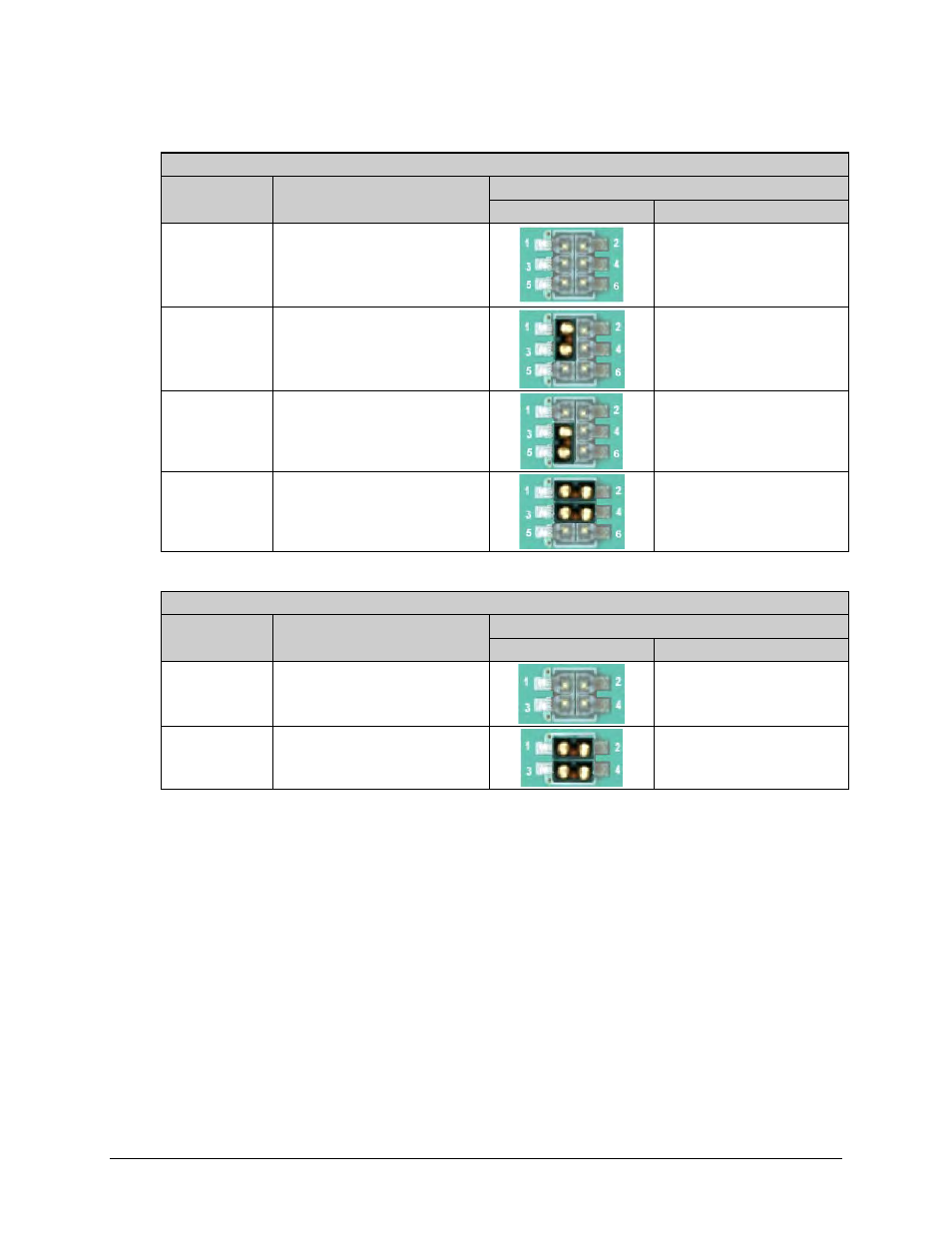
Table 5-3. CRS-316 “JP2” Jumper Settings
User Interface Jumper “JP2”
Modem
Control Signal Settings
Jumper Settings
Detail
Pins Jumped
CDM-625/A
CS_A/CTS & RS_A/RTS
Not Connected
N/A
(Note: TMI as shipped)
CDM-625/A
CS_A/CTS & RS_A/RTS
Loop Connected
at User DB-25 Connector
‘1’ to ‘3’
CDM-625/A
RTS
Controls Online Modem’s
Tx IF mute operation
‘3’ to ‘5’
SLM-5650A
CS_A/CTS & RS_A/RTS
Routed to Online Modem
‘1’ to ‘2’
‘3’ to ‘4’
Table 5-4. CRS-316 “JP3” through “JP6” Jumper Settings
User Interface Jumpers “JP3” through “JP6”
Modem
Control Signal Settings
Jumper Settings
Detail
Pins Jumped
CDM-625/A
DM/DSR, CS, RS, CS/CTS,
RS/RTS, DM/DSR
Not Connected
N/A
(Note: TMI as shipped)
SLM-5650A
DM/DSR, CS, RS, CS/CTS,
RS/RTS, DM/DSR
Routed to Traffic Modem
‘1’ to ‘2’
‘3’ to ‘4’