2 48v direct current (dc) power interface, 1 48v dc operation –power application – Comtech EF Data CRS-300 User Manual
Page 73
CRS-300 1:10 Redundancy Switch
MN/CRS300.IOM
Switch Connectors and Pinouts
Revision 19
3–19
o Pull the holder straight out, and then swing the holder away from the module.
•
Then, remove and replace the fuses as needed.
CAUTION – FOR CONTINUED OPERATOR SAFETY, ALWAYS REPLACE THE FUSES
WITH THE CORRECT TYPE AND RATING.
•
Finally, reseat the fuse holder in the IEC power module.
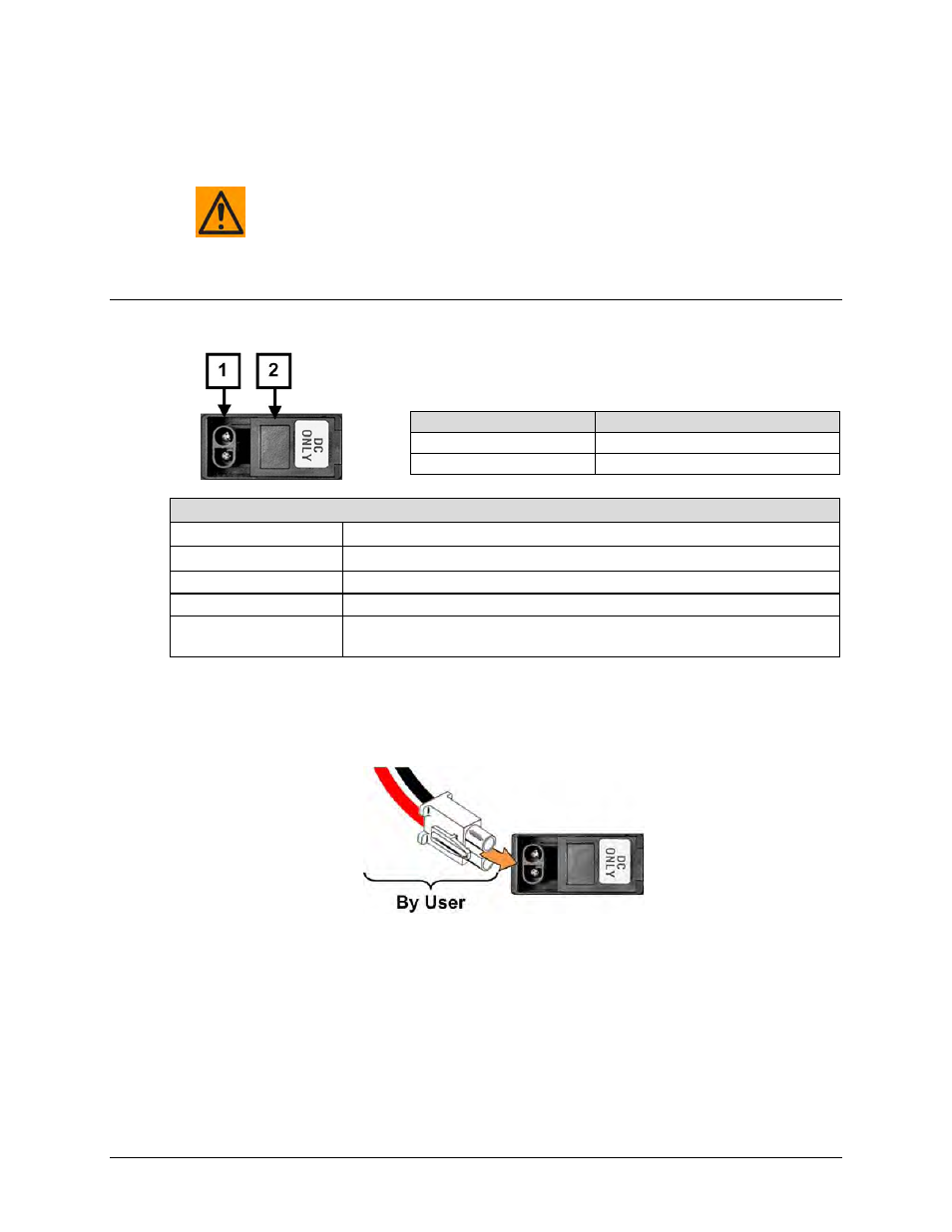
3.3.2.2 48V Direct Current (DC) Power Interface
Feature
Description
1
Power Cord Connector
2
Press Fit Fuse Holder (NOT USED)
DC Power Specifications
Input Power
50 watts, 2 Amps maximum
Input Voltage
48 volts DC (±20%) nominal (38-60 volts)
Connector Type
Corcom PS series
Mating Connector
Corcom GA210 or Molex 03-12-1026
Fuse Protection
While this interface features a fuse holder that is press-fit into the body of the IEC
power module, the CRS-300 chassis features an internal electronic resettable fuse.
Figure 3-8. Chassis DC Power Interface (CRS-250 DC Power Supply Module)
3.3.2.2.1 48V DC Operation –Power Application
Figure 3-9. Apply DC Power
To apply DC power to the CRS-300 (typical for each module):
•
First, plug the user-supplied, male keyed DC power lead connector into the mating female
connector until the lock tab engages. Number 18 AWG minimum wires are recommended.
•
Then, connect the user-supplied DC power leads to the power source.