Figure 5-5, Table 5-2 – Comtech EF Data CRS-300 User Manual
Page 177
Advertising
CRS-300 1:10 Redundancy Switch
MN/CRS300.IOM
Modem, RMI/TMI, and Switch Configuration
Revision 19
5–13
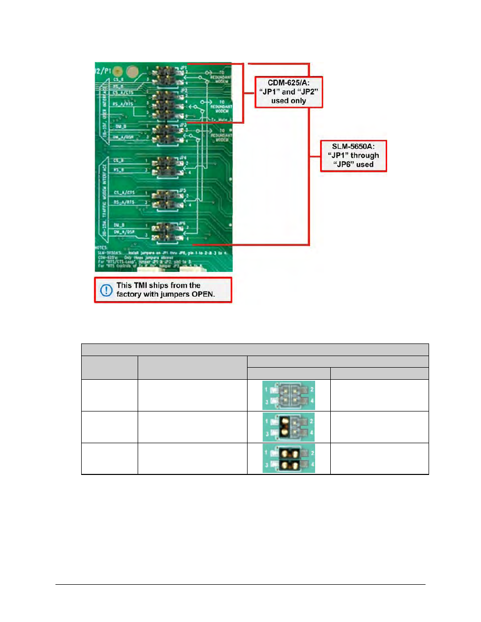
Figure 5-5. CRS-316 “JP1” through “JP6” Jumper Detail (As Shipped)
Table 5-2. CRS-316 “JP1” Jumper Settings
User Interface Jumper “JP1”
Modem
Control Signal Settings
Jumper Settings
Detail
Pins Jumped
CDM-625/A
CS_B & RS_B Signals
Not Connected
N/A
(Note: TMI as shipped)
CDM-625/A
CS_B to RS_B
Loop Connected
at User DB-25 Connector
‘1’ to ‘3’
SLM-5650A
CS_B & RS_B
Routed to online modem
‘1’ to ‘2’
‘3’ to ‘4’
Advertising
See also other documents in the category Comtech EF Data Equipment:
- CDD-880 (124 pages)
- CDM-800 (130 pages)
- ODMR-840 (184 pages)
- CDM-750 (302 pages)
- CDM-840 (244 pages)
- SLM-5650A (420 pages)
- CTOG-250 (236 pages)
- CDM-700 (256 pages)
- CDM-760 (416 pages)
- CDM-710G (246 pages)
- CDM-600/600L (278 pages)
- CDMR-570L (512 pages)
- CDM-625 (684 pages)
- CDM-625A (756 pages)
- CDD-564A (240 pages)
- CDD-564L (254 pages)
- CLO-10 (134 pages)
- MCED-100 (96 pages)
- CDMR-570AL (618 pages)
- CDM-600 LDPC (2 pages)
- BUC Power Supply Ground Cable (2 pages)
- MPP70 Hardware Kit for CDM-570L (4 pages)
- MPP50 Hardware Kit for CDM-570L (4 pages)
- CDM-625 DC-AC Conversion (4 pages)
- CDM-625 DC-AC Conversion with IP Packet Processor (4 pages)
- DMDVR20 LBST Rev 1.1 (117 pages)
- DMD2050E (212 pages)
- DMD-2050 (342 pages)
- DMD1050 (188 pages)
- OM20 (220 pages)
- QAM256 (87 pages)
- DD240XR Rev Е (121 pages)
- MM200 ASI Field (5 pages)
- DM240-DVB (196 pages)
- MM200 (192 pages)
- CRS-150 (78 pages)
- CRS-280L (64 pages)
- CRS-170A (172 pages)
- CRS-180 (136 pages)
- SMS-301 (124 pages)
- CiM-25/8000 (186 pages)
- CiM-25 (26 pages)
- CRS-500 (218 pages)
- CRS-311 (196 pages)
- CIC-20 LVDS to HSSI (26 pages)