4 optional crs-350 esc switch, Figure 1-24 – Comtech EF Data CRS-300 User Manual
Page 41
CRS-300 1:10 Redundancy Switch
MN/CRS300.IOM
Introduction
Revision 19
1–15
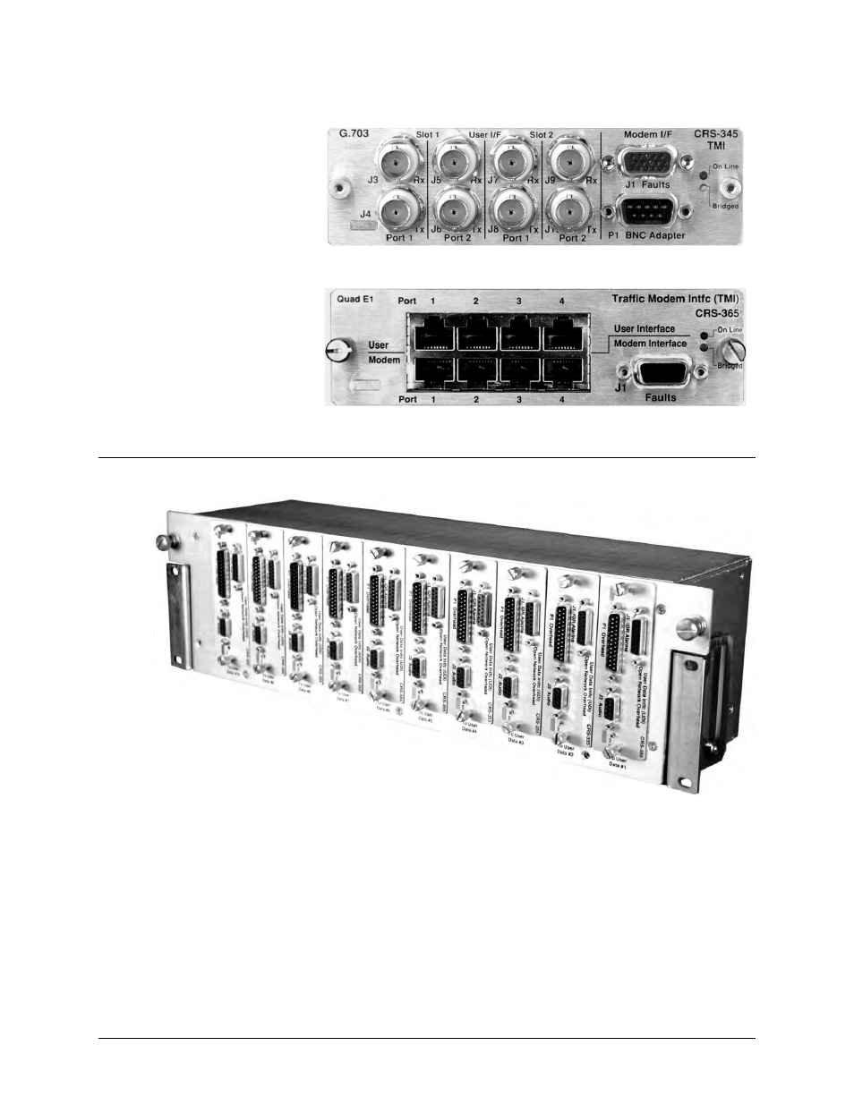
Figure 1-22. CRS-345 TMI
G.703 (4 ports)
(PL/11495-1)
FOR USE WITH
CDM-700 ONLY
(8X) BNC Male HD-15 Female
DB-9 Makle
Figure 1-23. CRS-365 TMI
E1 (1-4 ports) (PL/12985-1)
FOR USE WITH
CDM-Qx/QxL ONLY
(4X) RJ-45
(4X) RJ-45 HD-15 Female
1.4 Optional CRS-350 ESC Switch
Figure 1-24. CRS-350 ESC Switch – Front Panel
The CRS-350 Engineering Service Channel (ESC) Switch is intended for use with the CDM-600/L,
CDM-625/A, and SLM-5650/5650A modems. The CRS-350 is constructed as a 3RU-high, rack-
mounting chassis designed for mounting to the back of a 19-inch rack. See Figure 2-2 in
Chapter
2. INSTALLATION
for an installation example.
Figure 1-24 shows the user interface side of the CRS-350 ESC Switch. Here, you have access to
the Audio, Overhead, and IRD connector interfaces featured on the CRS-355 User Data Interface
(UDI) (Figure 1-25).