3 asi connectors, bnc (crs-325), 4 8 khz idr connector, rj-45f (crs-330) – Comtech EF Data CRS-300 User Manual
Page 63
CRS-300 1:10 Redundancy Switch
MN/CRS300.IOM
Switch Connectors and Pinouts
Revision 19
3–9
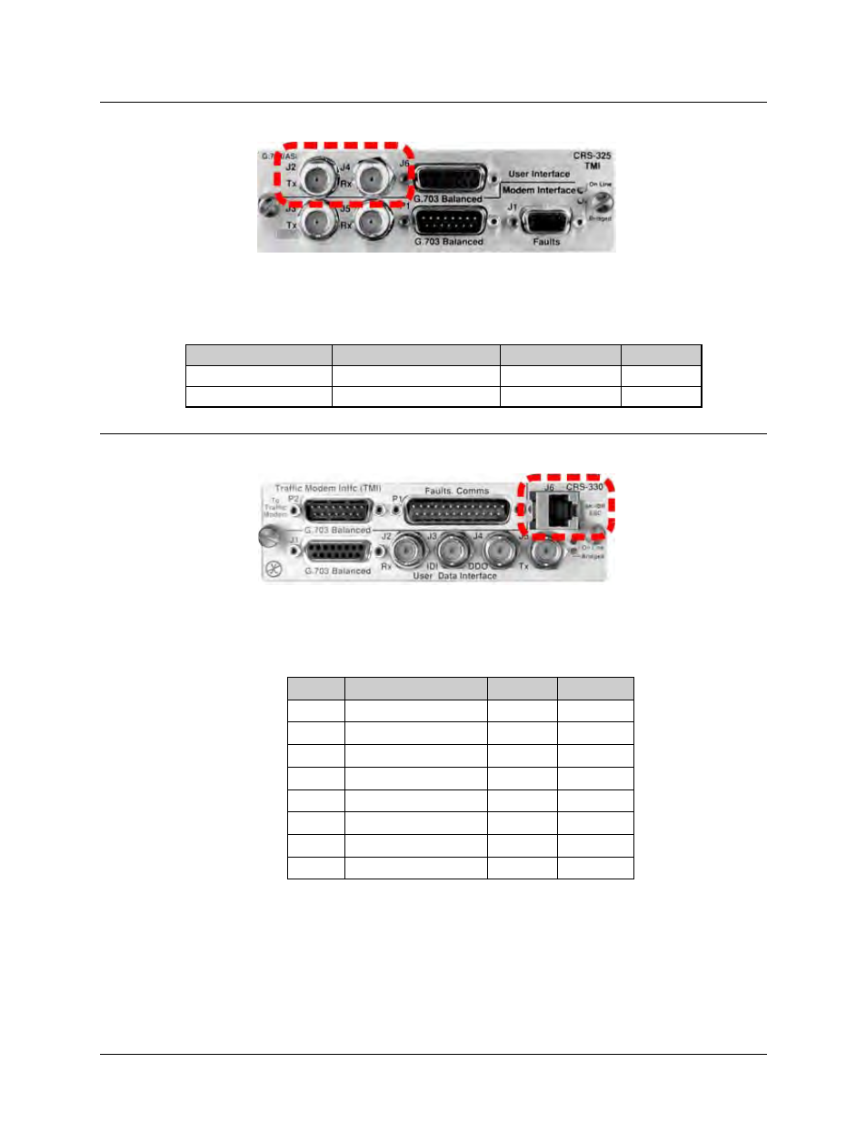
3.2.2.3 ASI Connectors, BNC (CRS-325)
These BNC female connectors provide the Actuator Sensor Interface (ASI) User Data Interface on
the CRS-325 TMI.
Table 3-6. ASI Connectors
BNC Connector
TMI CRS-325 Ref Des
Signal Function
Direction
Tx
J2
Tx, ASI
In
Rx
J4
Rx, ASI
Out
3.2.2.4 8 kHz IDR Connector, RJ-45F (CRS-330)
See Table 3-7 for the RJ -45F connector pinouts. This port provides the EIA-422 clock and data for
the 8 kHz IDR Engineering Service Channel (ESC) connector “J6” on the CRS-330 TMI.
Table 3-7. 8 kHz – IDR ESC Connector
Pin
Signal Function
Name
Direction
1
Tx Data+
SD+
In
2
Tx Data-
SD-
In
3
Rx Data+
RD+
Out
4
Tx Clock+
ST+
Out
5
Tx Clock-
ST-
Out
6
Rx Data-
RD-
Out
7
Rx Clock+
RT+
Out
8
Rx Clock-
RT-
Out