Comtech EF Data SMS-758 User Manual
Page 103
Advertising
SMS-758 Modem Protection Switch
Theory of Operation
MN/SMS758 Rev. 3
4–43
1
. . . . . . .
.
JP6
.
.
JP2
JP3
. .
. .
1
1
PRIME
INTERFACE
SWITCH
AS/1695
15
16
. . . .
. . . .
JP1
1
2
. . . .
1
JP7
. . . .
. . . .
.
JP2
. .
1
.
JP3
. .
1
Rev - Location
Rev A Location
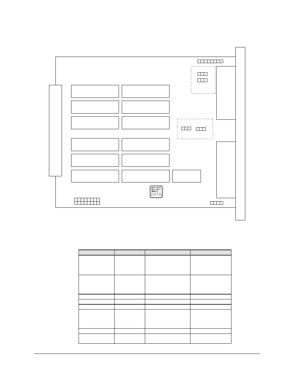
Figure 4-16. Prime IBS Jumper Diagram
Table 4-7. Prime IBS Jumpers
Operation
Jumper
Pins
Comments
Normal
JP1
5 through 6
7 through 8
13 through 14
15 through 16
Independent RST
and CTS
Special
JP1
1 through 2
3 through 4
9 through 10
11 through 12
CTS, tied to RTS,
TXD of ESC on
CTS lines
V.35, RS-422
JP2 and JP3
1 thorugh 2
G.703
JP2 and JP3
2 through 3
V.35, RS-422
JP6
Remove all jumpers
G.703
JP6
1 through 2
3 through 4
5 through 6
7 through 8
V.35, RS-422
JP7
Remove all jumpers
G.703
JP7
1 through 2
3 through 4
Advertising