2 connector pinouts – Comtech EF Data SMS-758 User Manual
Page 73
Advertising
SMS-758 Modem Protection Switch
Theory of Operation
MN/SMS758 Rev. 3
4–13
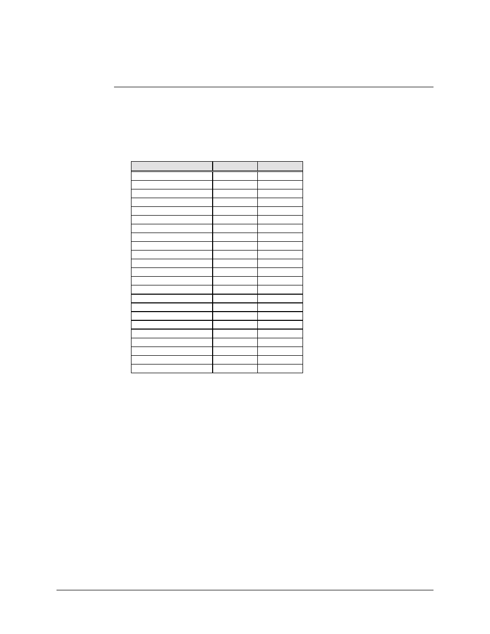
4.6.1.2 Connector Pinouts
A 37-pin female D connector provides interface for the RS-422/449 and
MIL-STD-188-114/RS-449 interface.
Screw locks provide mechanical security for the mating connector.
Signal Function
Name
Pin #
Signal Ground
SG
1,19,20,37
Send Data
SD-A
4
SD-B
22
Send Timing
ST-A
5
ST-B
23
Receive Data
RD-A
6
RD-B
24
Request To Send
RS-A
7
RS-B
25
Receiver Timing
RT-A
8
RT-B
26
Clear To Send
CS-A
9
CS-B
27
Data Mode
DM-A
11
DM-B
29
Receiver Ready
RR-A
13
RR-B
31
Terminal Timing
TT-A
17
TT-B
35
Master Clock
MC-A
16
MC-B
34
Modulator Fault
MF
3
Demodulator Fault
DF
21
Note: MF and DF inputs are only on the prime and backup modem interface connectors,
not the terrestrial data connector.
Advertising