1 led indicators, 2 keypad and lcd display – Comtech EF Data SMS-758 User Manual
Page 40
Operation
SMS-758 Modem Protection Switch
3–2
MN/SMS758 Rev. 3
Any keypad activity provides an interrupt to the processor, which then scans the keypad.
After the input has been recognized, the processor takes the appropriate action.
All switch functions are accessible to the operator from the front panel through the [F1]
and [F2] keys, the [PREV] key, and the [NEXT] key.
Proper operation of the switch depends on its proper configuration and setup. The
following sections describe the front panel and its operation in detail.
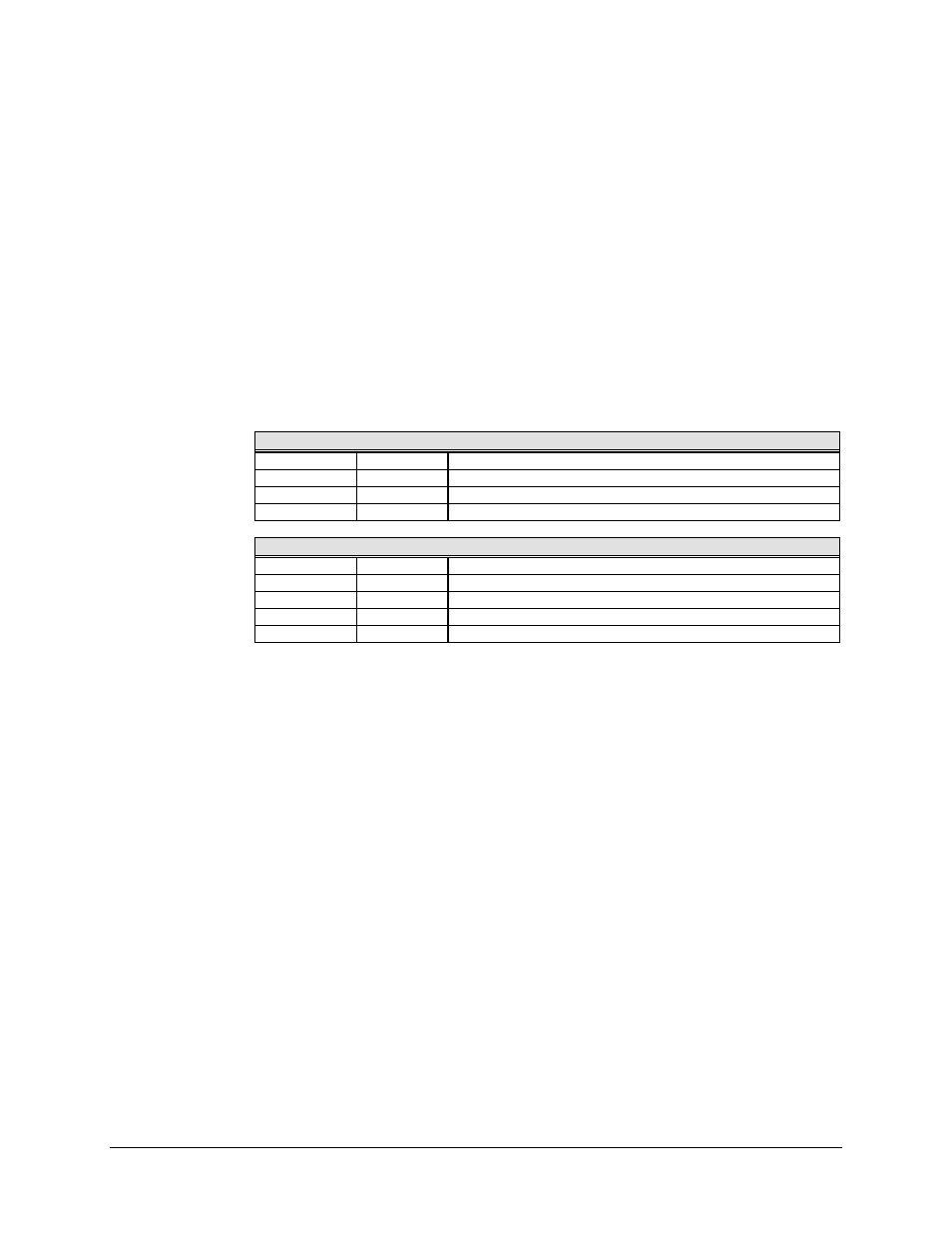
3.1.1 LED Indicators
Nine LEDs on the front panel indicate the general switch status and summary fault
information, as follows:
Faults
M:N
Red LED
Lights if M:N fault condition occurs.
MOD
Red LED
Lights if a modulator operation fault occurs.
DEMOD
Red LED
Lights if demodulator operation fault occurs.
BATTERY
Red LED
Lights if the M&C battery voltage is low.
Status
POWER ON
Green LED
Lights when power is applied to the switch.
AUTO
Green LED
Lights when the switch is in the automatic operating mode.
LOCAL
Green LED
Lights when the switch is in the local operating mode.
REMOTE
Green LED
Lights when the switch is in the remote operating mode.
BYPASS
Green LED
Lights when the switch is in the bypass operating mode.
3.1.2 Keypad and LCD Display
The keypad and LCD display provide an interface for the local operator to access the
menus that configure and operate the switch. The keypad includes the following keys:
•
Numbers 0 through 9
•
Decimal
•
[ENT] key
•
[F1] and [F2] keys
•
[NEXT] and [PREV] keys
The [F1], [F2], [NEXT], and [PREV] keys control the hierarchical menu structure.
Menus provide for local setup, configuration, and operation.
Each menu contains a portion of the switch control, or setup algorithm.
Only a limited knowledge of the switch is required, as the menus are self-prompting, and
all options are displayed.