Chapter 4: theory of operation, 1 monitor and control, Chapter 4. theory of operation – Comtech EF Data SMS-758 User Manual
Page 61
MN/SMS758 Rev. 3
4–1
Chapter 4.
THEORY OF OPERATION
4.1 Monitor and Control
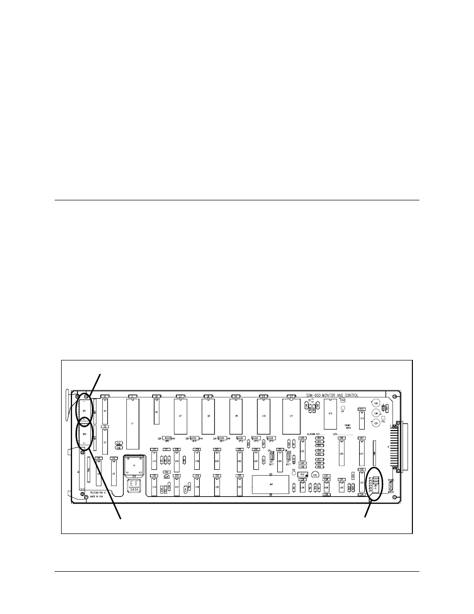
A sophisticated microcontroller performs the monitor and control functions of the
switch. The module, called the “Monitor and Control” (M&C), plugs into slot 5 of the
switch chassis (refer to Figure 4-1 for a drawing of the M&C, and Figure 1-3 for the
location in the chassis).
The M&C gathers status and provides extensive fault monitoring. The M&C monitors
the switch configuration and updates other modules within the switch, as required.
Switch configuration parameters are stored in battery-backed RAM to provide total
recovery after a power-down.
A local front panel interface and a remote communications interface provide user access
to all switch functions.
JUMPERS JP1 THROUGH JPX
SWITCH PACK (SP2)
ADDRESS
SWITCH PACK (SP1)
PARITY AND BAUD RATE
Figure 4-1. Monitor and Control