Comtech EF Data SMS-758 User Manual
Page 27
SMS-758 Modem Protection Switch
Introduction
MN/SMS758 Rev. 3
1–11
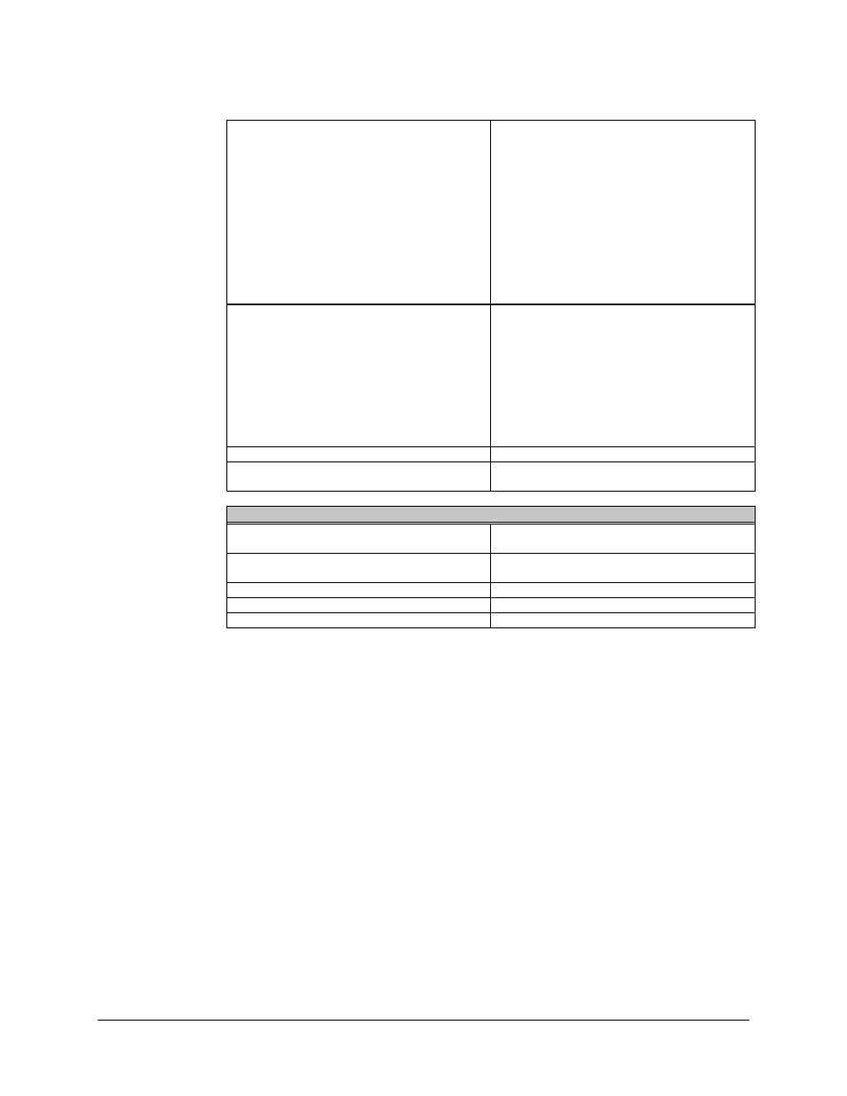
Indicators:
Front Panel LEDs
48-character display
Power supply on, controller and power supply
alarm, demodulator system failure, modulator
system failure, low battery alarm, auto mode,
local mode, remote mode, and bypass mode.
Prime and backup modulator and
demodulator status (fault and online status),
active modulators and demodulators (prime
and backup), modem address, modem
interface, modem uplink and downlink,
priority, delay, configuration, and fault menus.
Alarm Reporting:
Controller Fault Alarm
System Fault Alarm
Demodulator Fault Alarm
Form C relay contact to indicate controller or
power supply failure.
Form C relay contact to indicate any non-
catastrophic failure.
Form C relay contact to indicate all
demodulators faulted and a probable IF loss.
Operational Modes
Auto, Local, Remote, and Bypass.
Controls
Complete control of all M:N functions from the
front panel, or through the remote interface.
General
Input Voltage
90 to 264 VAC (self-adjusting).
-48 VDC optional.
Line Power
40W maximum when both power supplies are
operating.
Line Frequency
47 to 63 Hz.
Size
19" W x 22" D x 12.20" H.
Weight
50 lbs.