Chapter 3: operation, 1 front panel description, Chapter 3. operation – Comtech EF Data SMS-758 User Manual
Page 39
MN/SMS758 Rev. 3
3–1
Chapter 3.
OPERATION
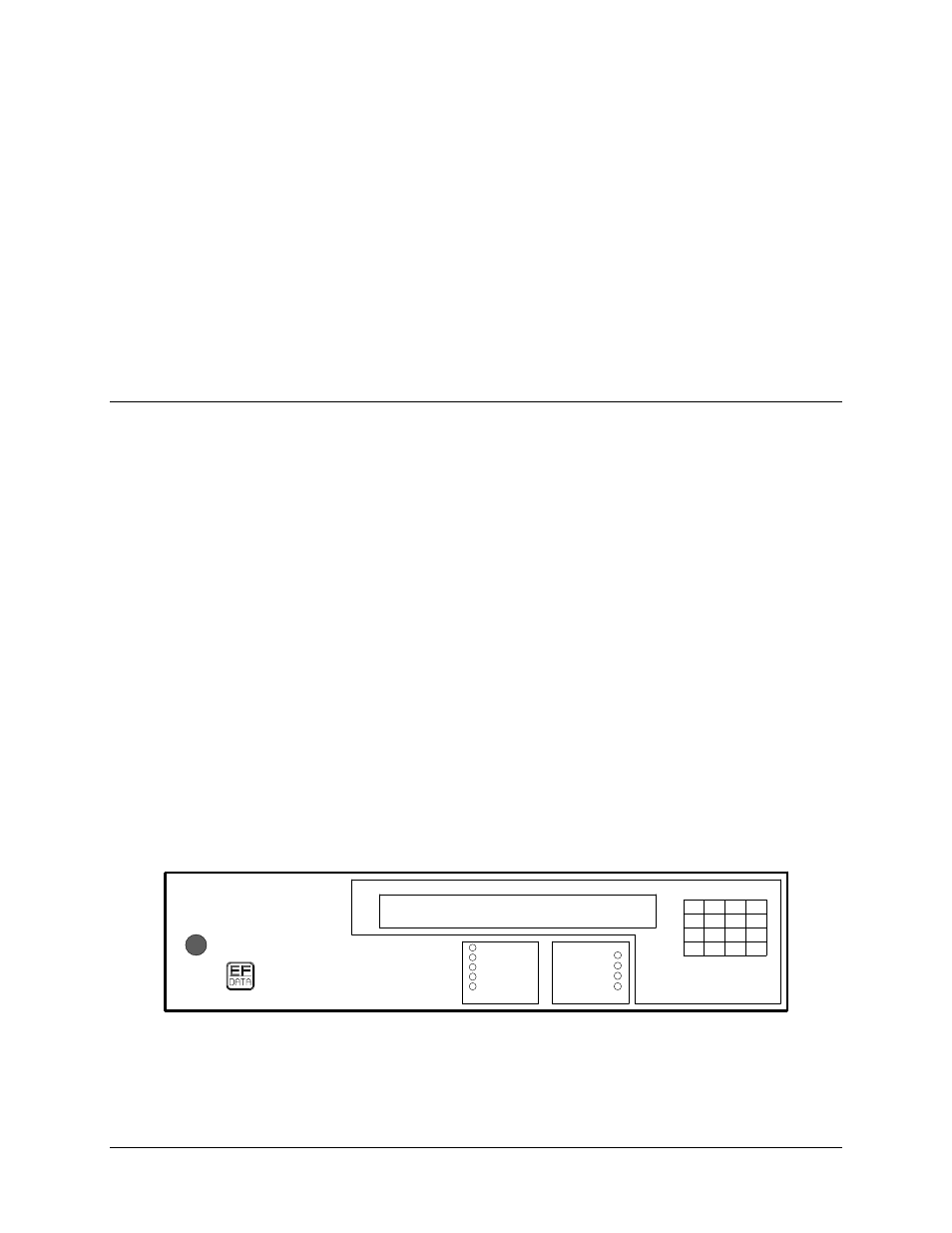
3.1 Front Panel Description
The switch front panel (Figure 3-1) provides the local interface to configure, operate, and
monitor the switch:
•
A 48-character, 2-line LCD display in the upper-front panel displays options and
status for the operator.
•
Nine LEDs grouped under the LCD display provide mode and fault status at a
glance.
•
A 16-key keypad to the right allows the operator to perform setup, configuration,
and operation functions.
•
An audible beeper signals the pressing of a keypad key.
The display, LEDs, and beeper are mapped into address space of the external bus
structure. The display updates every second, and the LEDs and beeper update as needed.
ENT
3
6
9
F1
F2
NEXT
PREV
.
0
1
2
4
5
7
8
SMS-758 MODEM PROTECTION
SWITCH SWX.XX PRESS NEXT
SMS-758
M:N SWITCH
STATUS
POWER
AUTO
LOCAL
REMOTE
BYPASS
BATTERY
MOD
DEMOD
M:N
FAULTS
Figure 3-1. SMS-758 Front Panel