Comtech EF Data SMS-758 User Manual
Page 82
Theory of Operation
SMS-758 Modem Protection Switch
4–22
MN/SMS758 Rev. 3
4.6.3.2 Connector Pinouts
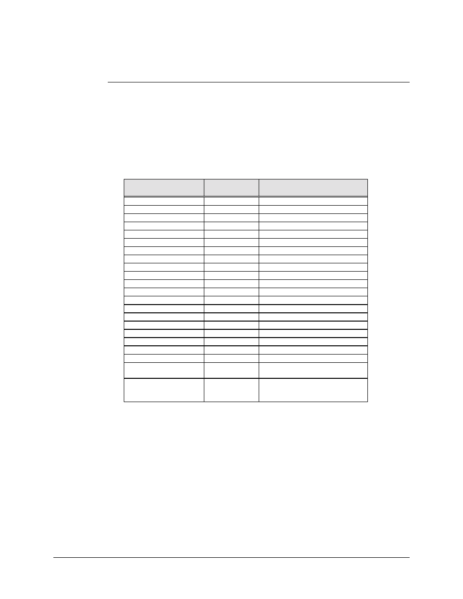
4.6.3.2.1 V.35 Option
The V.35 interface has been converted from the 34-pin block connector (refer to
Figure 4-4) to a 25-pin D connector (refer to Figure 4-6) that is accessible from the back
panel. Screw locks are provided for mechanical security of the mating connector.
Pin #
(25-Pin)
Pin #
(34-Pin Block)
Signal Name
1
A
Ground
7
B
Ground
14
P
Send Data A
2
S
Send Data B
25
U
Serial Clock Transmit External A
24
W
Serial Clock Transmit External B
18
Y
Serial Clock Transmit A
15
a (AA)
Serial Clock Transmit B
16
R
Receive Data A
3
T
Receive Data B
19
V
Serial Clock Receive A
17
X
Serial Clock Receive B
4
C
Request to Send
5
D
Clear to Send
6
E
Data Set Ready
8
F
Receive Line Signal Detect
22
c (CC)
External Reference Clock A
23
d (DD)
External Reference Clock B
20
m (MM)
Modulator fault
21
n (NN)
Demodulator fault
9, 10, 11, 12, and 13
No connection in 25-pin
connector
H, J, M, N, Z, b (BB),
e (EE), f (FF), h (HH),
j (JJ), k (KK), and l (LL)
No connection in 34-pin block