C.1 external connections, C.1.1 d/l switch input (j7), C.1.2 d/l switch output (j16) – Comtech EF Data SMS-758 User Manual
Page 170
7 Downlink Option
SMS-758 Modem Protection Switch
C–2
MN/SMS758 Rev. 3
C.1 External Connections
The external connections for the 7 downlink option are slightly different than the standard
SMS-758.
Make sure the rear panel sticker supplied with this appendix has been properly installed.
The only connectors that are different are J7 through J16, the downlink inputs, and backup
demod outputs.
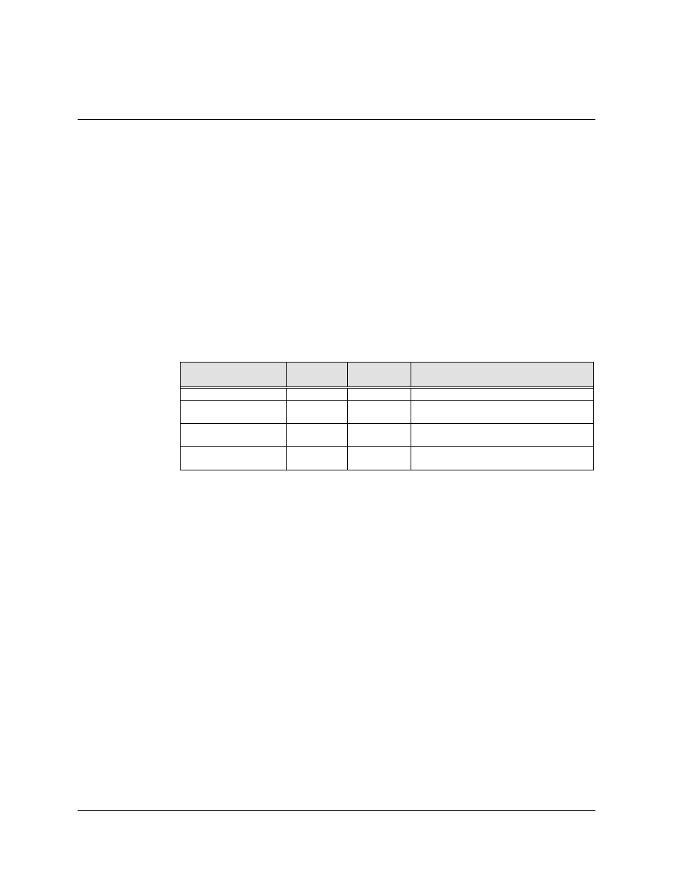
Table 2-1 lists the connectors for the 7 downlink option operation. All other connectors are
the same as described in Chapter 2 of the manual.
The use of each of these connectors is described in the following paragraphs.
Table 2-1. 7 Downlink Option Connectors
Name
Ref.
Desig.
Connector
Type
Function
D/L SWITCH INPUT
J7
BNC
DOWNLINK SWITCH INPUT
D/L SWITCH
OUTPUT
J16
BNC
DOWNLINK SWITCH OUTPUT
DOWNLINK INPUTS
J8 to J10
J12 to J15
BNC
DOWNLINK IF INPUTS
BACKUP DEMOD
J11
BNC
DOWNLINK OUTPUT TO BACKUP
DEMOD
C.1.1 D/L Switch Input (J7)
This is the downlink switch input connector. When using the 7 downlink option, connect a
cable from J16, D/L Switch Out, to J7, D/L Switch In. This enables downlink inputs 5
through 7.
When the 7 downlink option is not being used, this connector is a downlink input to backup
modem 1.
C.1.2 D/L Switch Output (J16)
This is the downlink switch output connector. As described above, when using the
7 downlink option, this connector enables downlink inputs 5 through 7, when connected to
J7.
When the 7 downlink option is not being used, this connector is the backup demod #2
output.