5 relay-remote/fault (j6) – Comtech EF Data SMS-758 User Manual
Page 36
Installation
SMS-758 Modem Protection Switch
2–8
MN/SMS758 Rev. 3
2.4.5 Relay-Remote/Fault (J6)
This 25 pin connector provides both input and output signals. The inputs are contact
closures or logic-level remote control inputs. The outputs are form C relay contact
closures for controller fault, M:N fault, and demodulator system fault.
Refer to Sections 3.2.4, 3.2.5, and 4.3 for more information on the relay-remote and fault
functions.
The relay-remote input and fault status interface connects through a 25-pin female D
connector. Screw locks provide mechanical security for the mating connector.
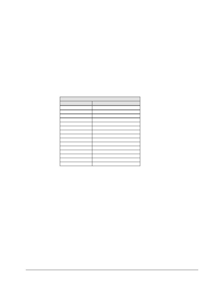
Relay-Remote Input and Fault Output Interface
Pin No.
Name
1
Controller Fault COM
2
Controller Fault NC
3
Controller Fault NO
4
Relay-Remote Input 0
5
Relay-Remote Input 1
6
Relay-Remote Input 2
7
Relay-Remote Input 3
8
Demodulator Fault COM
9
Demodulator Fault NC
10
Demodulator Fault NO
11
M:N Fault COM
12
M:N Fault NC
13
M:N Fault NO
14 through 24
No Connection
25
Ground
2.4.6 Downlink Inputs (J7 through J10, J12 through J15)
These are the downlink input connectors. These connections provide the inputs to the
downlink switching matrix:
•
J7 through J10 are the inputs to backup modem 1.
•
J12 through J15 are the inputs to backup modem 2, when the switch is
configured for 4 downlinks/2 backups.
Up to seven downlinks can be connected to the switch in the 7 downlink/1 backup
configuration. This option is available in the System menu on the front panel.
Downlink inputs that are not being used must be terminated into 75
Ω
.
Refer to Appendix C for more information on the 7 downlink/1 backup option.