1 specification, 2 connector pinouts – Comtech EF Data SMS-758 User Manual
Page 87
Advertising
SMS-758 Modem Protection Switch
Theory of Operation
MN/SMS758 Rev. 3
4–27
4.6.4.1 Specification
Circuits Supported
SD, RD, MC.
Switching Format
Modulator and demodulator signals switched individually
with dry contacts.
Contact Arrangement
Modulator signals:
2 poles.
Demodulator signals:
4 poles.
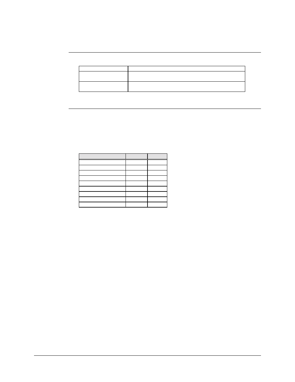
4.6.4.2 Connector Pinouts
The DS-1 and G.703 interface uses a 15-pin female D connector accessible from the
switch rear panel.
Screw locks provide mechanical security for the mating connector.
Signal Function
Name
Pin #
Shields
-
2,4
Send Data
SD-A
1
SD-B
9
Receive Data
RD-A
3
RD-B
11
Master Clock
MC-A
7
MC-B
8
Modulator Fault
MF
14
Demodulator Fault
DF
15
Note: MF and DF inputs are only on the prime and backup modem interface connectors,
not the terrestrial data connector.
Advertising