2 operation, 3 connector pinouts – Comtech EF Data SMS-758 User Manual
Page 95
SMS-758 Modem Protection Switch
Theory of Operation
MN/SMS758 Rev. 3
4–35
4.6.6.2 Operation
When configuring modem setup on the front panel, it is recommended to select #9 - IDR
2:N for the interface selection.
Note: The 1877 and 1879 interface will not work when #5 - IDR is selected in the
modem setup configuration. This interface cannot be used in conjunction with any
interface switch modules that only support 1 backup. These include the AS/0895 and
AS/0896 IDR modules. Check the rear of the switch and verify that none of the interface
switch modules are the AS/0895 or AS/0896 modules.
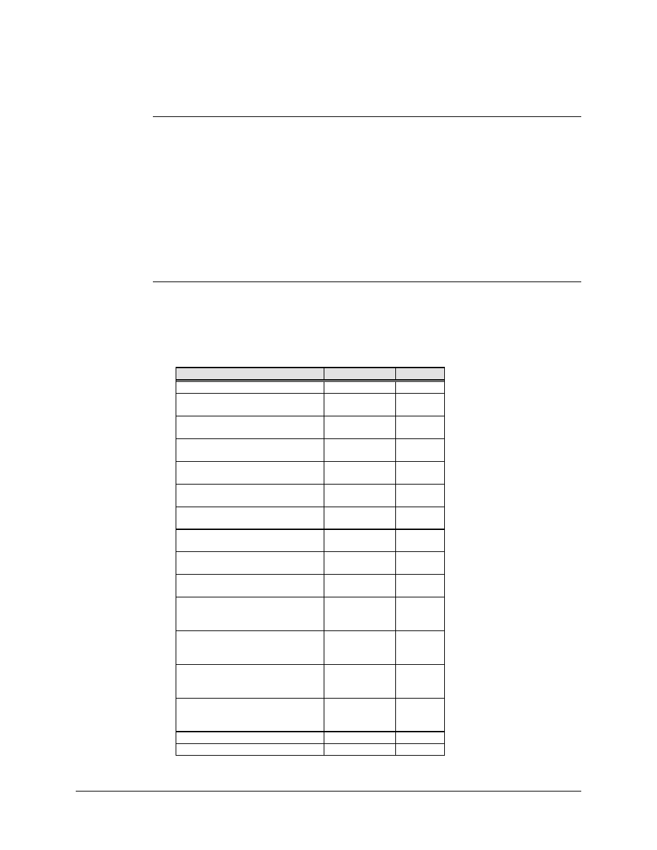
4.6.6.3 Connector Pinouts
The 2:N IDR interface uses a 50-pin female D connector.
Screw locks provide mechanical security of the mating connector.
Signal Function
Name
Pin #
Ground
-
1, 2
Send Data
SD-A
SD-B
34
18
Receive Data
RD-A
RD-B
36
20
Reference Clock
EXC-A
EXC-B
35
19
8 KBPS TX Data
TXD-A
TXD-B
37
38
8 KHz TX Clock Out
TXC-A
TXC-B
21
22
1 KHz TX Octet In
TXO-A
TXO-B
4
5
8 KBPS RX Data
RXD-A
RXD-B
39
40
8 KHz RX Clock Out
RXC-A
RXC-B
23
24
1 KHz RX Octet Out
RXO-A
RXO-B
6
7
Backward Alarm 1 Out
BWO1-C
BWO1-NC
BWO1-NO
8
25
41
Backward Alarm 2 Out
BWO2-C
BWO2-NC
BWO2-NO
9
26
42
Backward Alarm 3 Out
BWO3-C
BWO3-NC
BWO3-NO
10
27
43
Backward Alarm 4 Out
BWO4-C
BWO4-NC
BWO4-NO
11
28
44
Backward Alarm 1 In
BWI1
12
Backward Alarm 2 In
BWI2
13