8 if switch driver, 1 specifications, 2 theory of operation – Comtech EF Data SMS-758 User Manual
Page 107: Figure 4-19. switch driver board, Figure 4-20. if switch driver block diagram, Intf command decode
SMS-758 Modem Protection Switch
Theory of Operation
MN/SMS758 Rev. 3
4–47
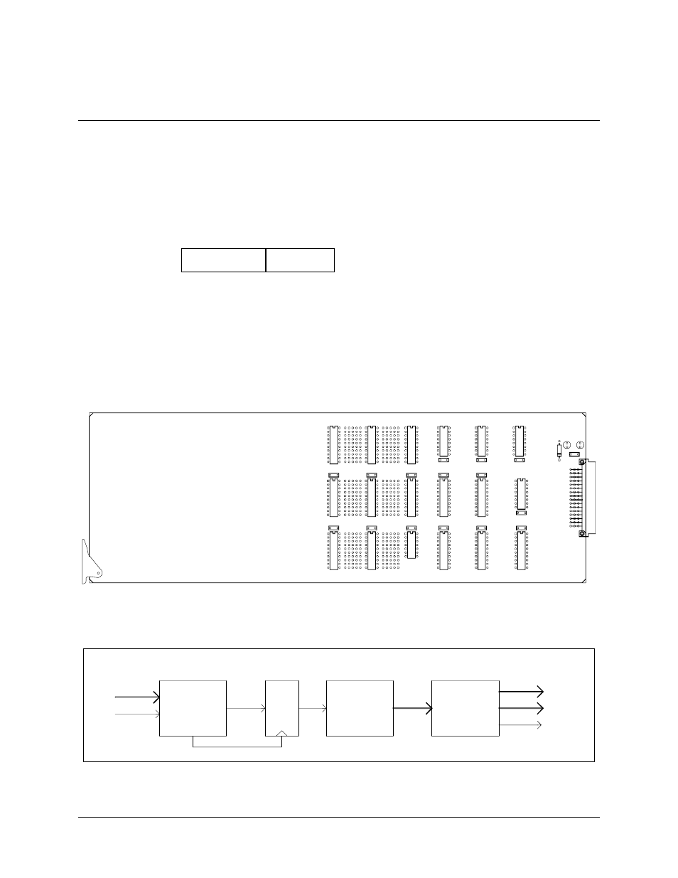
4.8 IF Switch Driver
The IF switch driver (Figure 4-19) is a 10.5” x 3.5” module that fits in slot 3 of the upper
front section of the switch chassis. It controls activation of the baseball switches on the
IF switch card. Refer to Figure 4-20 for a block diagram of the IF switch driver board.
4.8.1 Specifications
Power source
+5V
+12V
4.8.2 Theory of Operation
The M&C uses the address decoder/driver with an 8-bit data bus and 1 device select line
to control the switch driver. The switch driver decodes commands from the M&C card,
and activates the appropriate baseball switches on the IF switch accordingly.
IF SWITCH RELAY DRIVER
SMS-758
FSCM 4J515
AS/1316 REV _______
S/N ________________
Figure 4-19. Switch Driver Board
TO BASEBALL
SWITCH 1
X 22
BASEBALL
L
A
T
C
H
M&C
DATA BUS
FROM M&C
X 8
CARD SEL
INTF
COMMAND
DECODE
X 22
DRIVERS
+12V
TO BASEBALL
SWITCH 22
TO IF SWITCH
Figure 4-20. IF Switch Driver Block Diagram