Circuit diagram of inputs, Circuit diagram of outputs – QuickLabel 482 Pronto! User Manual
Page 135
Pronto! 482/486/682/863
8-45
In operation mode 2 and 3 “Print on demand”, connect the signal STA
(PIN13) with GND (PIN12)
•
PIN14 - RUEL - Reverse line (for all output signals)
•
PIN15 - 24P - Operating voltage +24V, Si T 100mA
The printer provides an operating voltage of 24V at PIN15.
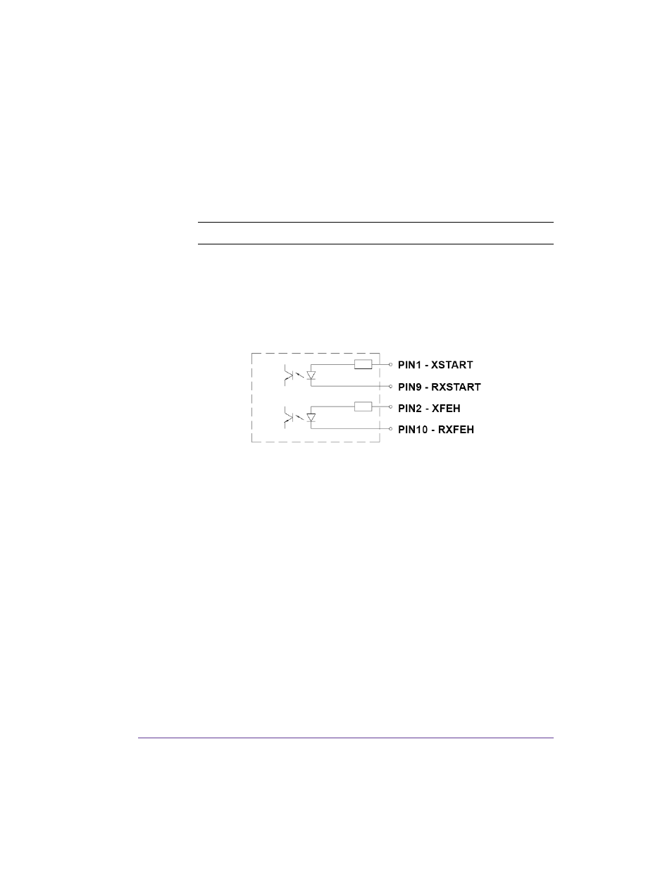
Circuit Diagram of Inputs
The XSTART and XFEH inputs are optocouplers with a current limiting
resistor of 2.2kW giving a voltage of 24V in the input circuit.
For each signal X[IN] there is a separate reverse line X[IN]R via the plug
connector. From that, the following matching pairs of signals result:
The external control device must be equipped with a 15 pin SUB-D connector.
For some operation modes the input signal STA (PIN13) has to be connected
with GND (PIN12).
Circuit Diagram of Outputs
All outputs are recognized through solid state relays Their outputs are
connected to one another on one-side. The joint line is lead to the plug
connector as a RÜL signal.
Caution: DO NOT connect any external voltage at PIN 15!