Circuit diagram of outputs, Circuit diagram of outputs -55 – QuickLabel 482 Pronto! User Manual
Page 145
Advertising
Pronto! 482/486/682/863
8-55
Minimum external circuit for operation with Pause Adapter PS7
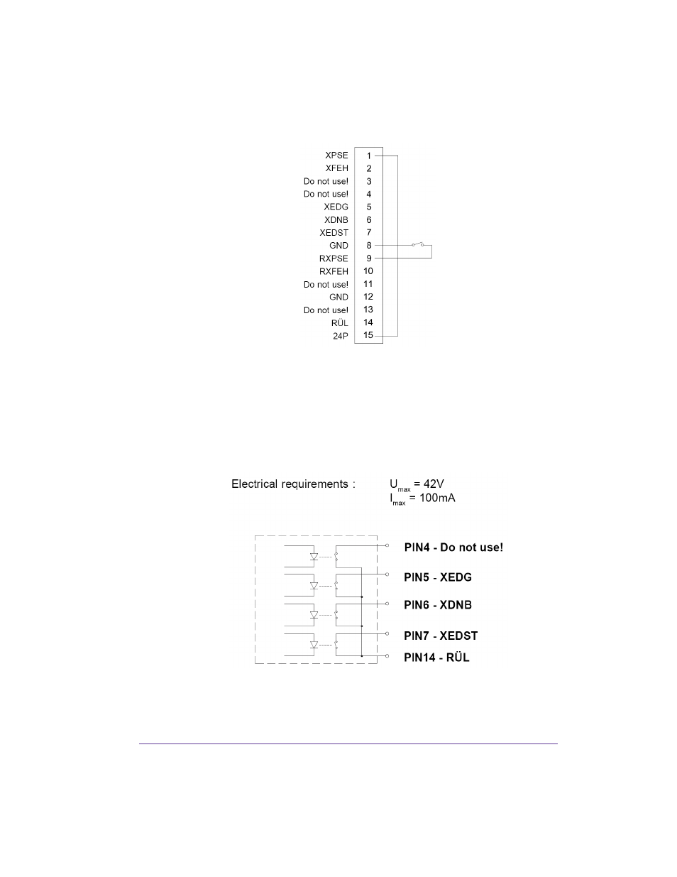
Circuit Diagram of Outputs
All outputs are recognized through solid state relays. Their outputs are
connected to one another on one-side. The joint line is lead to the plug
connector as a RÜL signal.
The switch function of the outputs is to open or close the contact between the
joint line RÜL and the respective output.
Advertising
This manual is related to the following products: