Installation, Hardware installation – Wavetronix Click 500 (programmable controller) (CLK-500) - User Guide User Manual
Page 122
CHAPTER 11 • CLICK 514
121
nected ports. However, only the RD (yellow) light will flicker in this case. The TD (green)
light is reserved for data originating from the Click 514.
Located on the front of the module below the DB-9 connector is a push-button labeled
Mode Switch. The push-button allows you to make selections from the menu. See the Op-
erating Modes section of this chapter for more information.
Installation
Before using the device, you will need to properly install the Click 514, SmartSensor HDs
and the necessary software.
Hardware Installation
Make sure that the Click 514 is installed on a T-bus with active power and RS-485 com-
munication.
The RS-232 DB-9 port on the front of the device is first used to make a connection between
the Click 514 and the computer running Click Supervisor. Then it will be used to connect
to the configuration and data ports on the DataBridge SDR2-CF device.
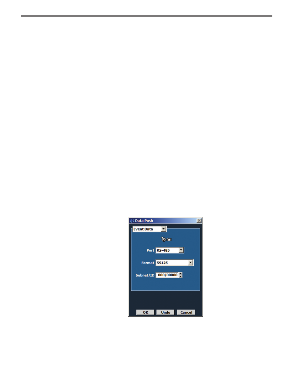
SmartSensor HD is configured separately using SmartSensor Manager HD over the RS-
232 port on the front of the corresponding Click 200 device. Once the SmartSensor HD is
connected and configured, you will need to enable data push over the RS-485 port using
SmartSensor Manager HD.
Figure 11.4 – SSMHD Data Push
Follow the instructions in the SmartSensor HD User Guide to install and configure the
SmartSensor HDs.