Configuration features, Warning – Wavetronix Click 500 (programmable controller) (CLK-500) - User Guide User Manual
Page 72
CHAPTER 8 • CLICK 511
71
Warning
The sixth switch of DIP switch 1 controls the mode of the device. Make sure that this
switch is in the OFF position. If it gets turned on, the device will enter Program mode
and all of the faceplate LEDs will turn off. To exit Program mode, power will need to
be cycled on the device.
Configuration Features
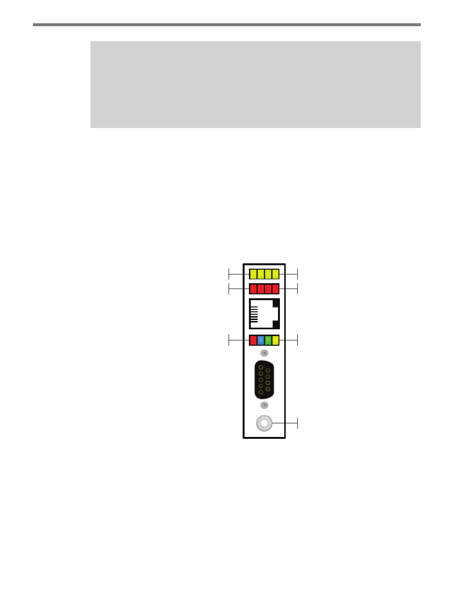
There are three banks of LEDs located on the front of the Click 511.
The yellow and red banks of LEDs display submenu selections and application information.
See the Operating Modes section of this chapter for more information.
The system LEDs (multicolored bank in the middle of the module) have dual functions:
they are activity indicators, reporting system status information, and they are also used in
selecting operation modes from the main menu.
Sub Menu 1
Sub Menu 2
Main Menu
Push-button
Yellow LEDs
Red LEDs
Multicolored LEDs
Figure 8.5 – Click 511 LEDs
The blue LED does not have an activity-indicating function. The other three LEDs indicate
system status as follows:
˽
PWR (red) lights up when the device has power.
˽
TD (green) lights up when the device is transmitting data.
˽
RD (yellow) lights up when the device is receiving data.
If the Click 511 receives data via one port it will forward (transmit) the data to the other