Connecting power, Serial communications, Real time clock – Wavetronix Click 500 (programmable controller) (CLK-500) - User Guide User Manual
Page 44: Rs-232 ports
CHAPTER 6 • CLICK 500
43
Real Time Clock
The real time clock on the Click 500 has a backup battery in order to maintain time in
the event of a power outage. However, like a wristwatch, this clock can drift forward and
backward by several seconds per day, so depending upon your application, you may need
to synchronize the clock.
Connecting Power
The Click 500 requires between 10 V and 30 V to be connected to the +DC and -DC pins on
the T-bus; the recommended voltage is 24 V. The easiest way to connect power to the T-bus
is to use a Click 201/202 AC to DC power supply (see Figure 6.3).
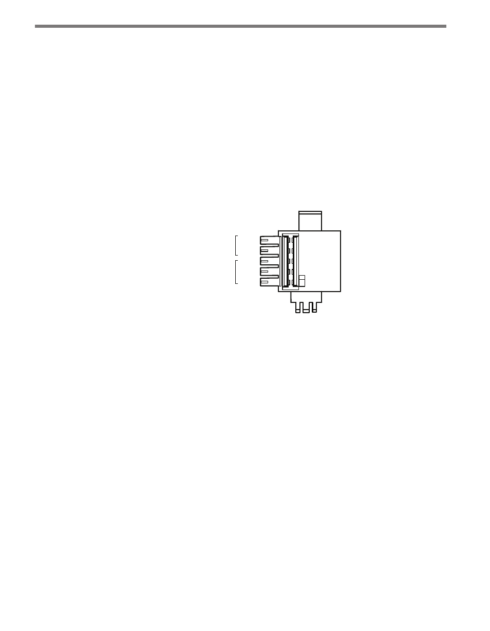
T-bus Connector
+DC
-DC
+485
-485
GND
RS-485
T-bus Port
Power
Supply
Figure 6.3 – Connecting Power through the T-bus
The GND, -DC, -I1 and -I2 ports (see Digital Inputs section) are all interconnected and
represent a common logic ground. The -DC terminal on the T-bus connector provides a
convenient termination point for DC power wiring. Likewise, the -I1 and -I2 terminals
provide a convenient termination point for the input common lines.
Serial Communications
The four independent serial ports are available through five serial port connectors.
RS-232 Ports
The two physically independent RS-232 serial ports are accessed via the DB-9 DCE con-
nector on the front of the module and a screw terminal connector on the top of the module.
Figure 6.4 shows the pin level descriptions for the RS-232 front connector.
The RS-232 front serial port is used to develop and debug applications when the device is
in program mode. This port can also be used in run mode to interact with other devices.
For example, in run mode this port is often used to interact with the computer-based Click
Supervisor device management software.