Installation – Wavetronix Click 500 (programmable controller) (CLK-500) - User Guide User Manual
Page 84
CHAPTER 9 • CLICK 512
83
See the Operating Modes section of this chapter for more information.
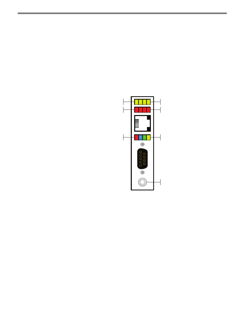
The system LEDs (multicolored bank in the middle of the module) have dual functions:
they are activity indicators, reporting system status information, and they are also used in
selecting operation modes from the main menu.
The blue LED does not have an activity-indicating function. The other three LEDs indicate
system status as follows:
˽
PWR (red) lights up when the device has power.
˽
TD (green) lights up when the device is transmitting data.
˽
RD (yellow) lights up when the device is receiving data.
Sub Menu 1
Sub Menu 2
Main Menu
Push-button
Yellow LEDs
Red LEDs
Multicolored LEDs
Figure 9.3 – Click 512 LEDs
If the Click 512 receives data via one port it will forward (transmit) the data to the other
ports. However, only the RD (yellow) light will flicker in this case. The TD (green) light is
reserved for data originating from the Click 512.
Located on the front of the module below the DB-9 connector is a push-button labeled
Mode Switch. The push-button allows you to make selections from the menu. See the Op-
erating Modes section of this chapter for more information.
Installation
Make sure that the Click 512 is installed on a T-bus with active power and RS-485 com-
munication.
If you are going to use your Click 512 in conjunction with a computer serial port and ter-
minal program, the RS-232 DB-9 port on the front of the device can be used to make a