Using the menu, Leds – Wavetronix Click 500 (programmable controller) (CLK-500) - User Guide User Manual
Page 52
CHAPTER 6 • CLICK 500
51
Voltage Threshold
1
2
3
4
5
6
22.9 VDC
–
–
–
–
–
ON
11.7 VDC
–
–
–
–
–
OFF
Table 6.4 – Voltage Supply Monitoring Circuit DIP Switch 2 Settings
Using the Menu
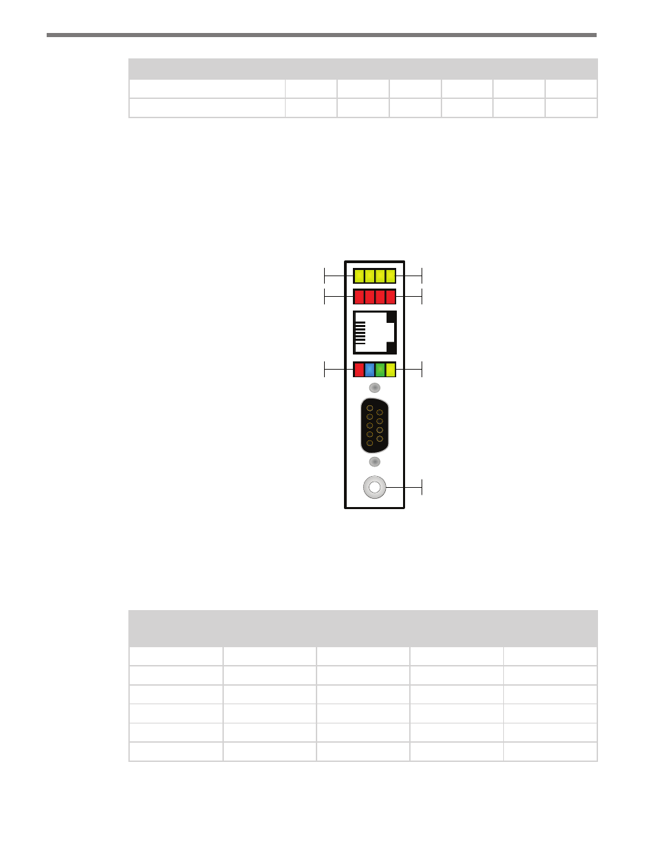
The hardware user interface consists of a push-button and 12 LED indicators that allow
you to access the menu and its custom operating functions. The push-button allows you to
control the state of the device, while the LEDs report status information (see Figure 6.11).
Sub Menu 1
Sub Menu 2
Main Menu
Push-button
Yellow LEDs
Red LEDs
Multicolored LEDs
Figure 6.11 – Click 500 User Interface Menu
LEDs
Table 6.5 below shows the state of the system LEDs when a mode or task is selected:
Mode/Task
Red System
LED State
Blue System
LED State
Green System
LED State
Yellow System
LED State
Blue
On
On
–
–
Blue Flash
Flashing
On
–
–
Green
On
–
On
–
Green Flash
Flashing
–
On
–
Yellow
Off
–
–
On
Yellow Flash
Flashing
–
–
On
Table 6.5 – LED State while Mode/Task is Selected