Wavetronix Click 500 (programmable controller) (CLK-500) - User Guide User Manual
Page 91
90
CHAPTER 9 • CLICK 512
variable
L_ft / V_fps
fixed
1 s
variable
Duration (fixed)
1
2
3
4
5
variable
Time to Point = SetbackDistance_ft / V_fps
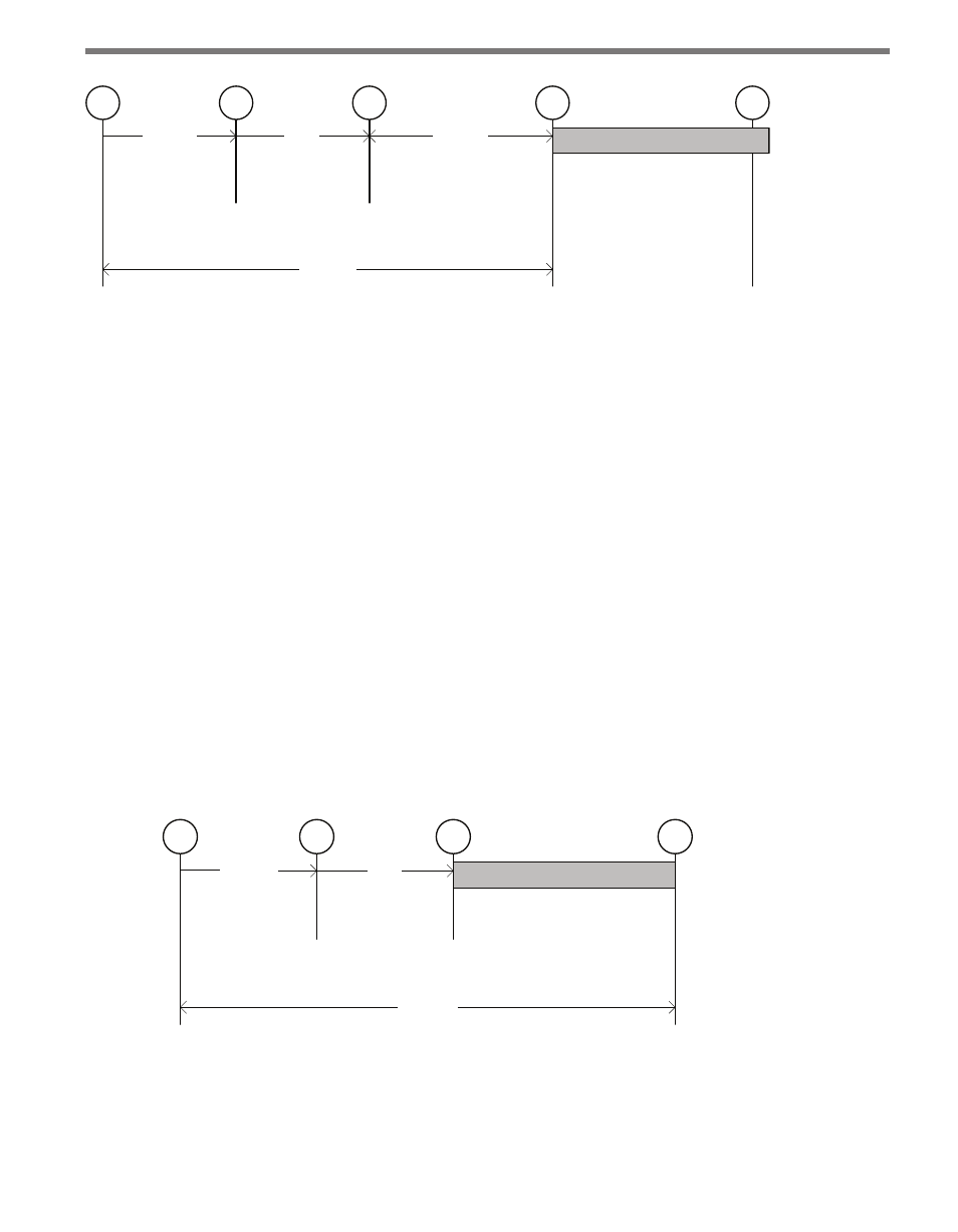
Figure 9.6 – Diagram for Fixed Location Timing Method
1 Front edge of vehicle enters beam.
2 Back edge of vehicle leaves beam. The time from point 1 to point 2 is variable and is
based on the length and speed of the vehicle.
3 Detection event is generated one second after the vehicle leaves the beam. This one-
second delay is fixed.
4 Output is activated when front-edge of vehicle reaches the selected trigger point (as-
suming constant speed).
5 Output is deactivated at the end of the duration.
The third method, the ASAP trigger method, provides a less uniform response because the
trigger is not synchronized. However, this method may be useful when the setback distance
is limited.
In order to trigger as soon as possible:
1 Select the None (Trigger Sync) configuration options.
2 Specify the duration in milliseconds.
The following diagram illustrates the basic timing of this option as a series of four steps.
Some portions of the timing are variable and others are fixed.
variable
L_ft / V_fps
fixed
1 s
Duration (fixed)
1
2
3
4
variable
Total Delay = L_ft / Vfps + 1 s
Figure 9.7 – Diagram for ASAP Timing Method
1 Front edge of vehicle enters beam.
2 Back edge of vehicle leaves beam. The time from point 1 to point 2 is variable and is
based on the length and speed of the vehicle.