Wavetronix Click 500 (programmable controller) (CLK-500) - User Guide User Manual
Page 57
56
CHAPTER 7 • CLICK 510
Sub Menu 1
Sub Menu 2
Main Menu
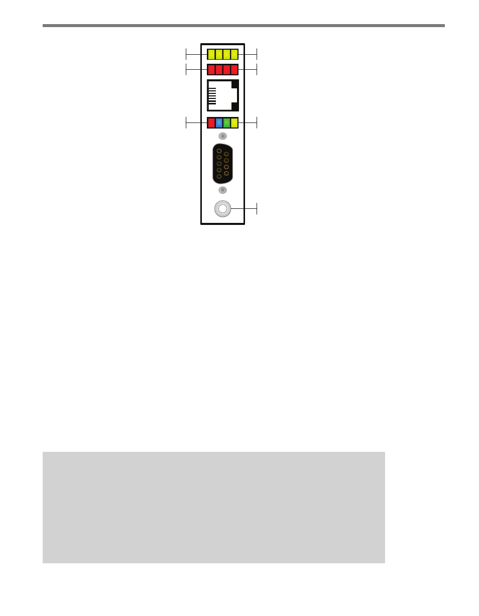
Push-button
Yellow LEDs
Red LEDs
Multicolored LEDs
Figure 7.3 – Click 510 Configuration Features
The yellow and red banks of LEDs display submenu selections and application information.
See the Operating Modes section of this chapter for more information.
The system LEDs (multicolored bank in the middle of the module) have dual functions:
they are activity indicators, reporting system status information, and they are also used in
selecting operation modes from the main menu.
The blue LED does not have an activity-indicating function. The other three LEDs indicate
system status as follows:
˽
PWR (red) lights up when the device has power.
˽
TD (green) lights up when the device is transmitting data.
˽
RD (yellow) lights up when the device is receiving data.
If the Click 510 receives data via one port it will forward (transmit) the data to the other
ports. However, only the RD (yellow) light will flicker in this case. The TD (green) light is
reserved for data created by the Click 510.
Note
If you send a message request to a SmartSensor 105 via the front DB-9 port, you
will see the following: the RD (yellow) light flicker once when the message request is
received and then forwarded to the sensor (e.g. via an RS-485 port). The RD (yellow)
light flickers again when the message response from the sensor is received by the
Click 510 and forwarded to the front DB-9 port. The TD (green) light will not flicker at
all in this example.