Wavetronix Click 500 (programmable controller) (CLK-500) - User Guide User Manual
Page 13
12
CHAPTER 1 • THE POWER PLANT
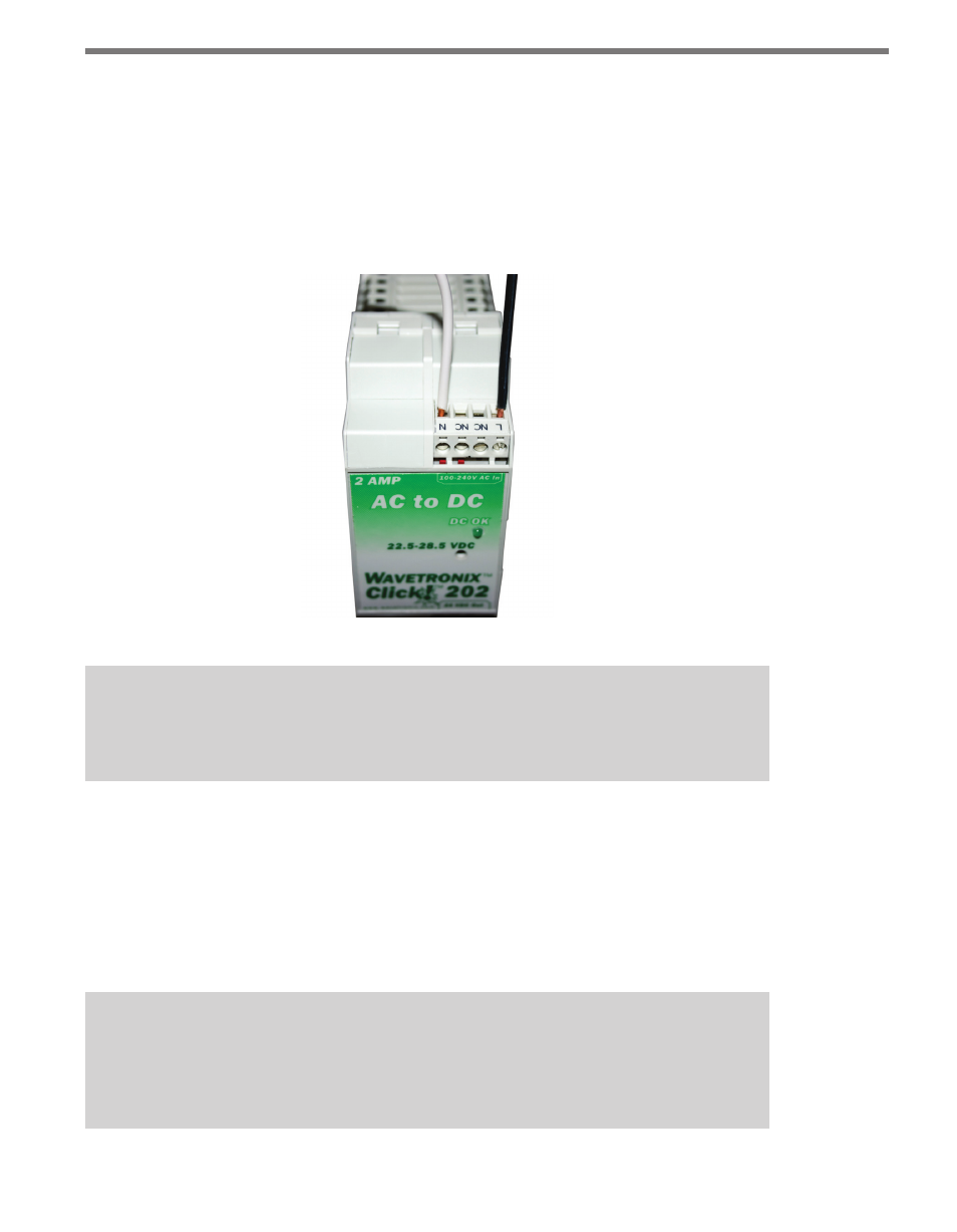
Wiring AC Power into the Click 201/202/204
Use the steps below to properly wire AC power to the top of the Click 201/202/204:
1 Using a rocking motion, mount the Click 202/202/204 to the DIN rail next to the Click
230.
2 Connect the power and neutral wires from the Click 230 into the screw terminals
marked L and N, respectively, on the side of the module marked 100–240V AC In.
Figure 1.3 – Wiring AC Power into the Click 201/202/204
Caution
Make sure power to AC mains is disconnected while wiring the AC input.
Wiring DC Power out of the Click 201/202/204
The screw terminals on the bottom of the devices are slightly different. The Click 202 and
204 have a single terminal block, while the Click 201 has two; it doesn’t matter which of
the two terminal blocks on the 201 you wire into. Connect one wire for DC power (red is
standard) to a screw terminal marked +. Connect a second wire as a ground wire (black is
standard) to either of the two terminals marked – (see Figure 1.4).
Note
Do not wire into the DCOK terminal; it provides only 20 mA and should only be used
to monitor the power supply.