Rs-485 ports – Wavetronix Click 500 (programmable controller) (CLK-500) - User Guide User Manual
Page 45
44
CHAPTER 6 • CLICK 500
RS-232 Front Connector
DCD
RD
TD
DTR
GND
DSR
RTS
CTS
RI
1
2
3
4
5
6
7
8
9
Figure 6.4 – RS-232 Front Connector
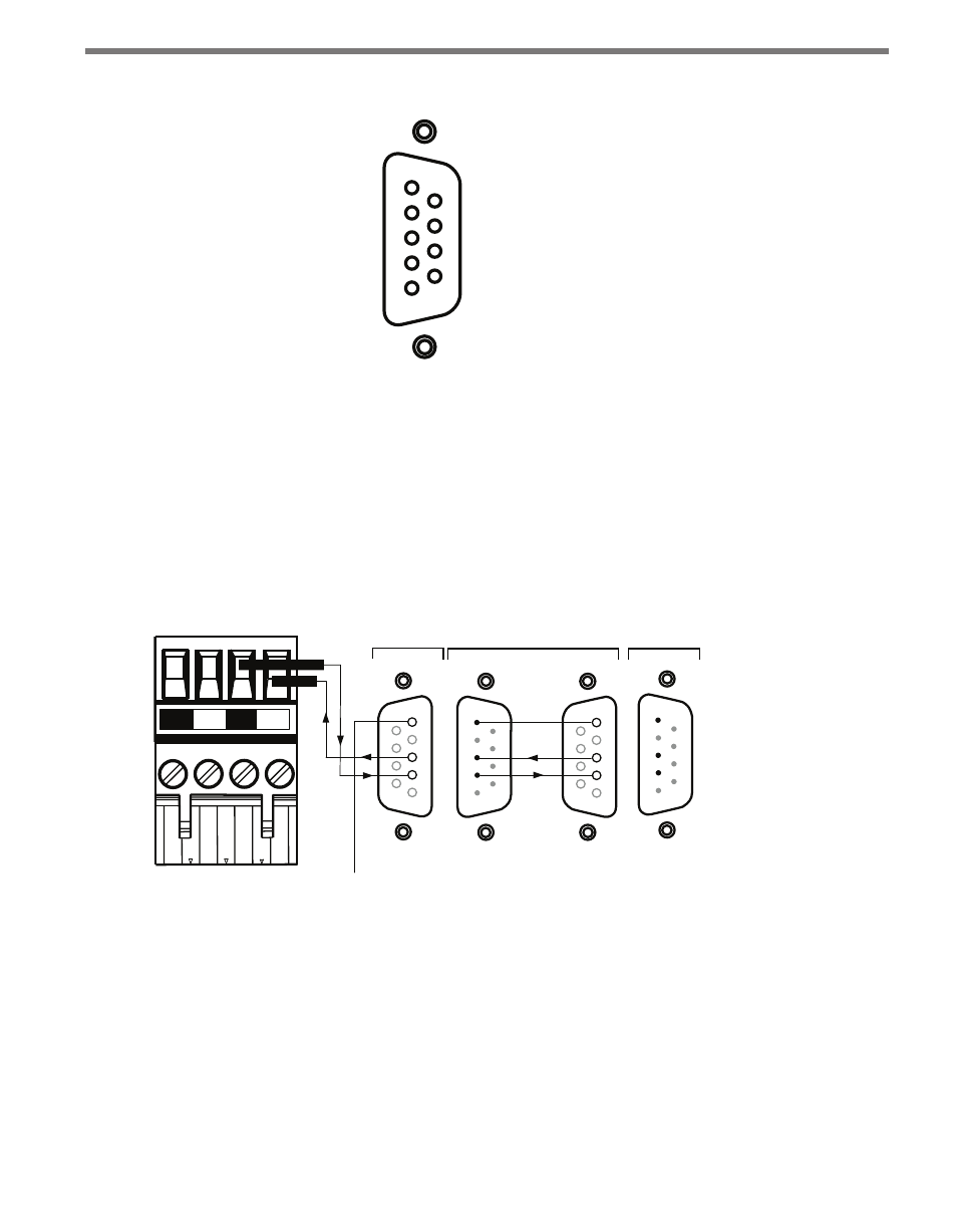
The left-side of Figure 6.5 shows the RS-232 pin level descriptions for the other serial port.
The right-side of this figure details the connections made to wire to a DCE DB-9 female
connector and then link to a computer via a straight-through serial cable. The TD and RD
labels on the serial cable are not referenced to the DCE device (Click 500) but rather to the
DTE device (PC). The arrows show the direction of flow; transmit data on the DTE device
becomes received data on the DCE device and vice-versa. This reversal of roles is why you
connect pin 2 of the DCE DB-9 female connector to the TD screw terminal and pin 3 to the
RD screw terminal.
NC
NC
TD
RD
RS-232 Top Connector
1
2
3
4
5
1
2
3
4
5
2
3
To GND on
RS-485 Connector
DB-9 Male
(Computer)
DCE
DTE
Serial Cable
DB-9 Female
GND
TD
RD
Figure 6.5 – RS 232 Top
RS-485 Ports
The RS-485 serial ports are located on the T-bus connector, the RS-485 terminal block on
top of the module and the RJ-11 connector located on the front of the module. The RS-485
terminal on the top of the module and the RJ-11 jack on the front are electrically connected
and represent a single serial port. Figure 6.6 below shows the RS-485 pin-level descriptions
for this ort. The other RS-485 serial port on the T-bus connector is physically independent.