Clean feed out, Clean feed out -27, Figure 3-13 – Grass Valley 1200 Installation User Manual
Page 101: Frame modules clean feed out, Figure 3-13. clean feed out
3-27
Frame Modules
Clean Feed Out
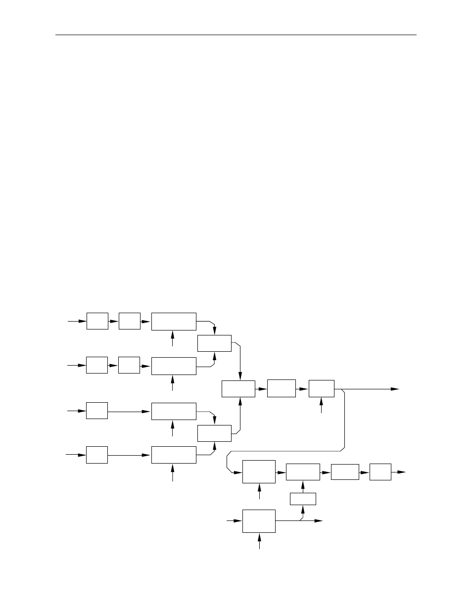
A and B Backgrounds enter into the Program Mixer Module from the
Crosspoint Module (see Figure 3-13). They each go through a Proc Amp
and then enter a Mixer circuit. The Mixer circuits use the Background A
and Background B Control signals to determine how much of each signal
will feed the Background Combiner circuit.
The Key 1 and Key 2 video go through buffers (the proc amps for the keys
are on the Key Processor Submodule). The mixer circuits then use the Key 1
and Key 2 Control signals to determine how much of each signal will go
into the Key Combiner circuit.
The outputs of the Key Combiner and the Background Combiner circuits
enter another Combiner circuit. There, the background video is combined
with the key video signal.
The results of all of these operations are kept at full accuracy until reaching
the limit and round circuit, which does two things: it rounds the results to
ten bits and prevents an overflow or underflow condition.
The final mixer combines the background and key signal with the border
control signal to create the Clean Feed Signal. This signal is sent both to the
DSK and to the Clean Feed Output. The Clean Feed Output is delayed and
unshaped if necessary before being sent to the output.
Figure 3-13. Clean Feed Out
RE-
CLOCK
PROC
AMP
RE-
CLOCK
PROC
AMP
RE-
CLOCK
RE-
CLOCK
BACKGROUND A
MIXER
COMBINER
BACKGROUND B
MIXER
KEY 1
MIXER
KEY 2
MIXER
COMBINER
COMBINER
LIMIT
AND
ROUND
MIXER
VARIABLE
DELAY
UNSHAPER
ENCODER
RE-
CLOCK
1 / KEY
VARIABLE
DELAY
Back-
ground A
Back-
ground B
Key 1
Video
Key 2
Video
Bkgd A
Control
Bkgd B
Control
Key 1
Control
Key 2
Control
CPU
Border
Control
CPU
Border Matte
Controller
Clean Feed Video
to DSK Mixer
Clean
Feed
Video
Key
to Key Output Selectors
Clean Key