Input modules, Serial input module, Parallel input module – Grass Valley 1200 Installation User Manual
Page 89: Input modules -15, Serial input module -15 parallel input module -15, Figure 3-4, Serial input module -15, Figure 3-5, Parallel input module -15, Frame modules
3-15
Frame Modules
Input Modules
Each of the Input Modules contains the circuitry for two serial or parallel
inputs. Both circuits in one module are identical. The circuits convert from
the ECL level signal on the cable to the TTL levels that are used in the
Model 1200. The video or key goes from the Input Module into the
Crosspoint Module.
Serial Input Module
The Serial Input Module (Figure 3-4) has two circuits. The first converts
from serial to parallel video and the second converts from ECL to TTL
signal levels. The output of the Serial Input Module is a TTL version of
Parallel video. The clock is stripped off the serial signal and sent to the
Crosspoint Module.
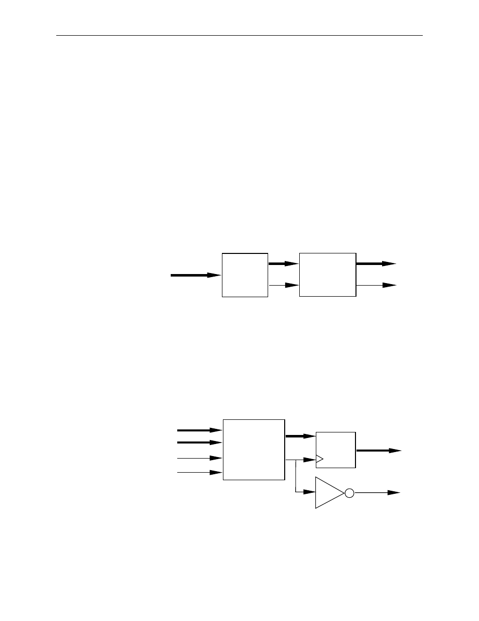
Figure 3-4. Serial Input Module
Parallel Input Module
The Parallel Input Module (Figure 3-5) converts the signal from ECL to
TTL and then runs the signal through a latch to align all of the bits. The
clock is sent to the Crosspoint Module.
Figure 3-5. Parallel Input Module
Serial Video In
VID_IN 0:9
VIDCLK
SERIAL
DECODER
ECL TO TTL
CONVERTER
Video 0 : 9
/ Video 0 : 9
VCP
/ VCP
VID_IN 0 : 9
V/CLK 1
ECL to TTL
CONVERTER
LATCH