Model 1200 functional overview, Model 1200 functional overview -6, Figure 1-2 – Grass Valley 1200 Installation User Manual
Page 22: Model 1200 simplified functional block diagram -6
1-6
Section 1 Ñ System Overview
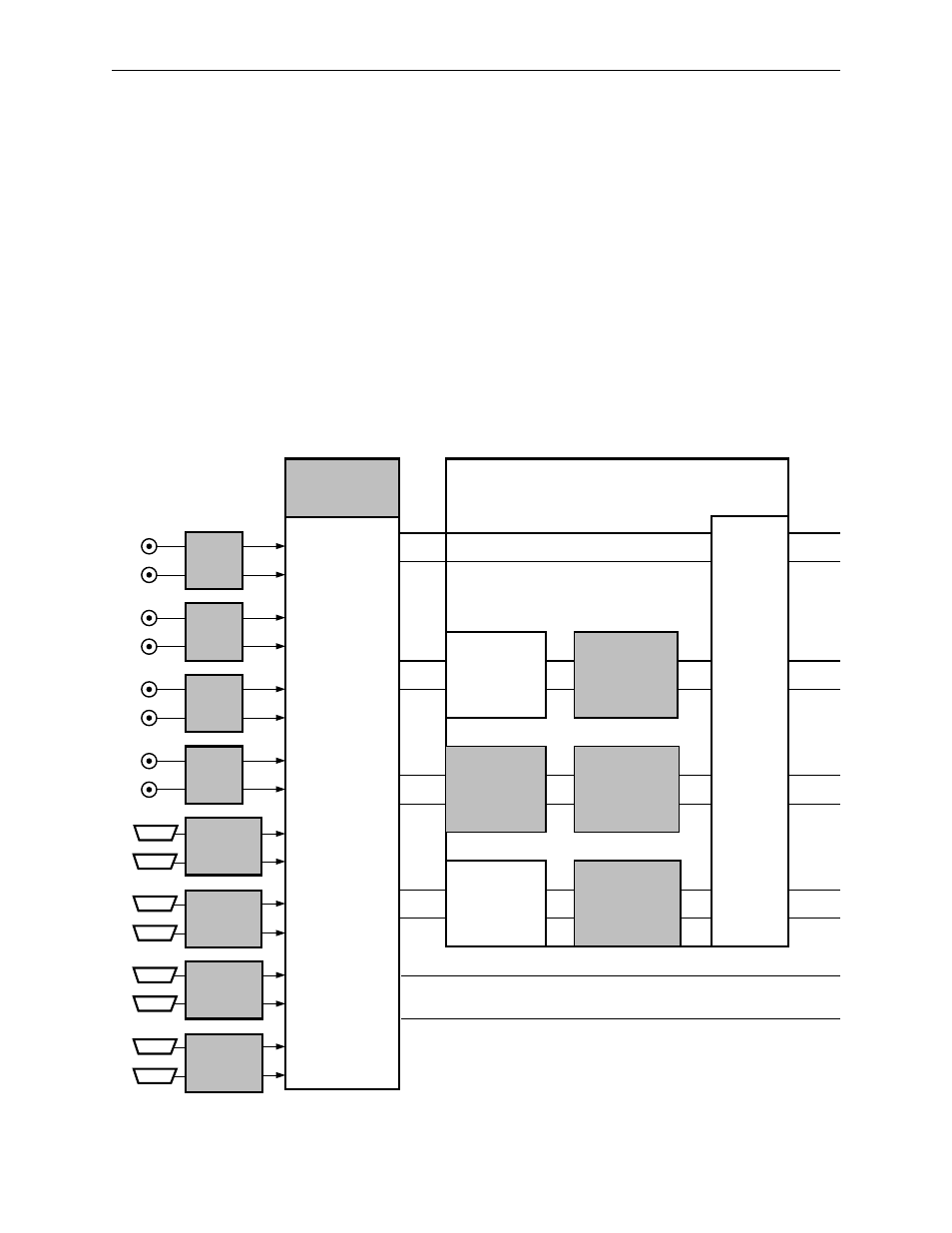
Model 1200 Functional Overview
The Model 1200 architecture (Figure 1-2) consists of a single mix/effects
system with two keyers and a downstream keyer. Video inputs selected on
the background crosspoint buses enter a pair of program and preview
mixers. Video and key inputs selected on the key crosspoint bus are first
processed in the keyer circuits.
If effects send mode is off, the keyer outputs go directly to the mixers, and
any aux bus selections go directly to the aux outputs. If effects send mode
is on, the source and fill outputs of one of the keyers are routed via the aux
bus outputs to a DPM.
Figure 1-2. Model 1200 Simplified Functional Block Diagram
KEYER CARRIER AND
EFFECTS SEND
MODULE
MIX/EFFECTS
KEYER 1
DOWNSTREAM
KEYER
K
K
K
K
K
K
CROSSPOINT
MODULE
V
PROGRAM BACKGROUND
PRESET BACKGROUND
V
V
V
V
EFFECTS
SEND
AND
AUX BUS
SIGNAL
ROUTING
AUX 1
AUX 2
K
K
K
V
V
V
V
••••••••••••
••••••••••
••••••••••••
••••••••••
••••••••••••
••••••••••
••••••••••••
••••••••••
••••••••••••
••••••••••
••••••••••••
••••••••••
••••••••••••
••••••••••
••••••••••••
••••••••••
BORDERLINE
KEY EDGE
GENERATOR
OPTION
BORDERLINE
KEY EDGE
GENERATOR
OPTION
CHROMATTE™
4:2:2/4:4:4 CHROMA
KEY OPTION
SECOND
MIX/EFFECTS
KEYER
OPTION
BORDERLINE
KEY EDGE
GENERATOR
OPTION
SERIAL
INPUT
OPTION
PARALLEL
INPUT
OPTION
SERIAL
INPUT
OPTION
SERIAL
INPUT
OPTION
SERIAL
INPUT
OPTION
PARALLEL
INPUT
OPTION
PARALLEL
INPUT
OPTION
PARALLEL
INPUT
OPTION
Note: Digital video/key inputs and outputs may be
either serial or parallel as specified when ordered.