Control panel modules, Control panel modules -39, Figure 3-21 – Grass Valley 1200 Installation User Manual
Page 113: Panel overview -39, Control panel
3-39
Control Panel
Control Panel Modules
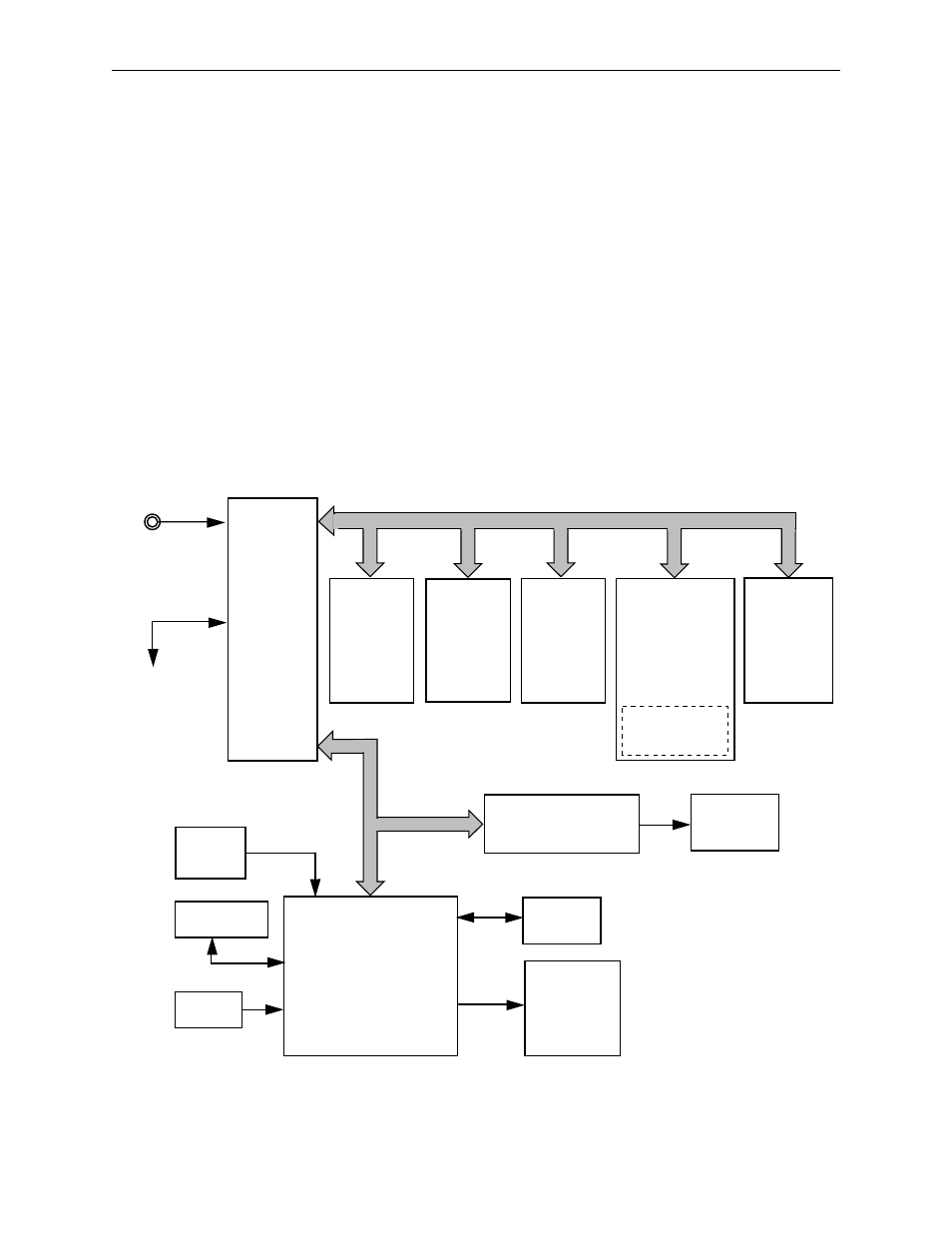
The Model 1200 Control Panel contains seven module assemblies: the
Control Panel I/O module (064919), the Control Panel MPU module
(064926), the Crosspoints module (064920), the E-MEM module (064921),
the Display Surround module (064922), the Matte/Key/Wipe module
(064923) with a circuit of Analog-to-Digital Data Acquisition System, the
Peripheral Enable module (064924), and the Flat Panel Display Driver
(Electroluminescent Adaptor). The Control Panel I/O board routes all
messages between the modules, the MPU, and the frame control processor.
Address decoding is contained on the Crosspoints, E-MEM, and Matte/
Key/Wipe modules. The Display Surround and Peripheral Enable
modules are too small to handle address decoding, so their address
decoding is done on the Crosspoints module. Panel analog inputs (lever
arm, joystick, and all rotary controls) are handled by the Analog-to-Digital
Data Acquisition system circuit located on the Matte/Key/Wipe module.
Figure 3-21. Panel Overview
Video Timing
Reference
Serial
Comm
to Video
Electronics
Frame
Power
Supply
Keyboard *
Mouse *
RDY/EPC-31 based
Personal Computer
Motherboard
(Control Panel MPU)
(064926)
VGA
Monitor *
Floppy
Disk Drive
Menu
Display
Video Graphics Array-to-
Electroluminescent
Adaptor
Analog-to-Digital
Data Acquisition
System
Industry Standard
Architecture Bus
(064919)
(064920)
(064921)
(064922)
(064923)
(064924)
I/O Module
Control Panel
Lower Left
Switch Board
Crosspoints
Module
Lower Right
Switch Board
E-MEM
Module
Upper Left
Switch Board
Display
Surround
Module
Upper Right
Switch Board
Matte/Key/Wipe
Module
Splash Left
Switch Board
Peripheral
Enable
Module
* Customer-supplied and optional
Input Output Processor Address, Data, Strobes
TP0715-03