Control processor module, Control processor module -11, Figure 3-2 – Grass Valley 1200 Installation User Manual
Page 85: Control processor module block diagram -11, Frame modules, The system boot, The operating system, The external interface, Calculations necessary to do the video functions, Reading system configuration
3-11
Frame Modules
Control Processor Module
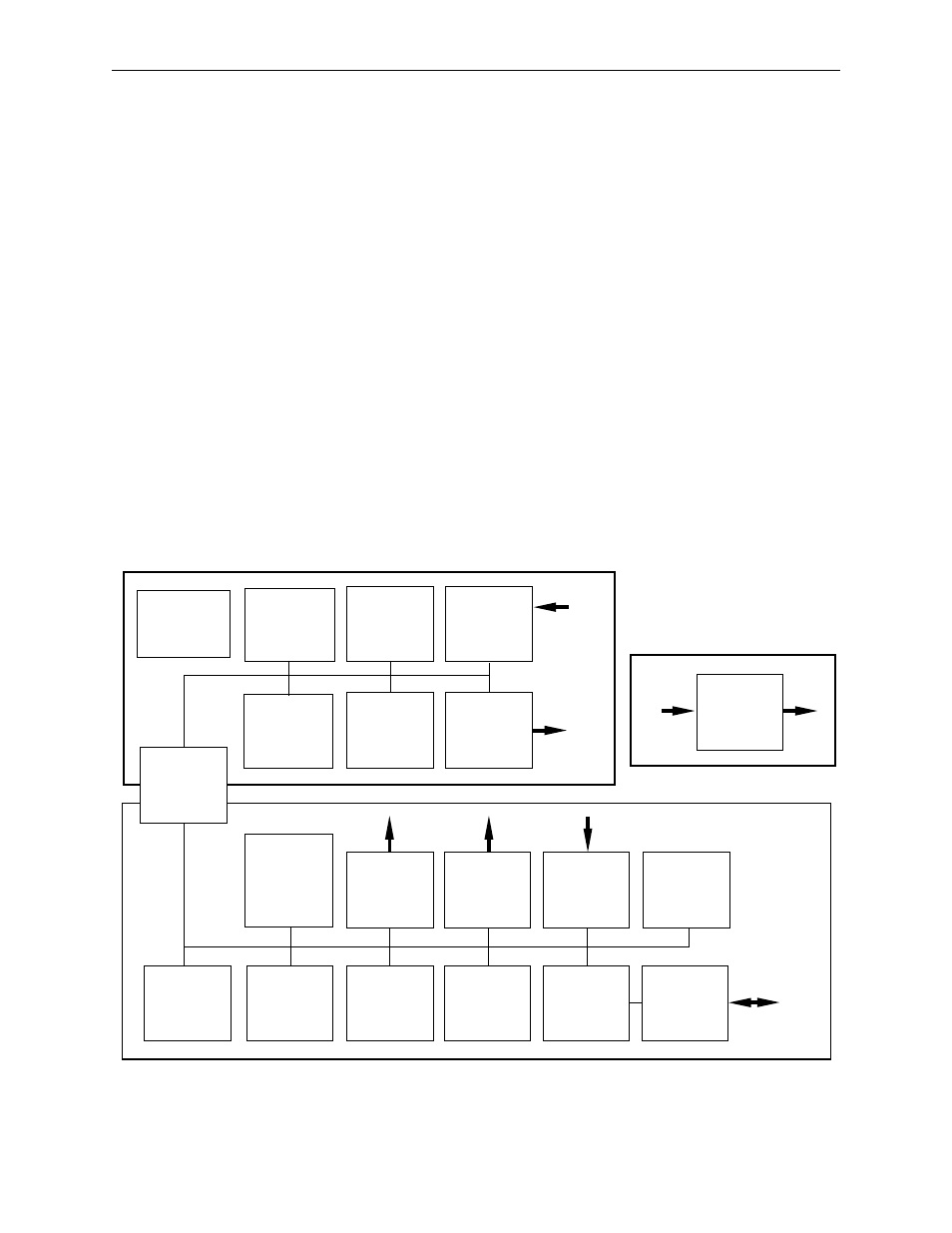
The Control Processor Module (Figure 3-2) has overall control of the
system. All of the control and interface functions originate here. There are
two microprocessors and associated circuitry on the module.
The 68302 I/O processor handles the following:
■
The system boot
■
The operating system
■
The external interface
■
The watchdog timer
The 68020 state processor handles the following:
■
The reading and writing between the control panel and the signal
processor frame
■
Calculations necessary to do the video functions
■
Reading system configuration
Figure 3-2. Control Processor Module Block Diagram
68881
MATH
COPROCESSOR
68020
STATE
PROCESSOR
PARAMETER
EEPROM
I/O
SENSING
RAM
FRAME
INTERFACE
68302
I/O
PROCESSOR
TALLY
RELAYS
GPI
OUTPUTS
GPI
INPUTS
SYNC
PULSE
GENERATOR
SUBMODULE
PANEL,
TTY, MODEM,
EDITOR, DPMS,
I/O
SERIAL
BUSES
MODULE
REVISION
CONTROL
BOOT
PROM
FLASH
EEPROM
RAM
BUS
ARBITRATOR
To
and
From
Frame
Modules
and
Submodules
Reference
Clocks
and
Syncs
FIELD LED
BACKGND LED
FIELD LED
BACKGND LED
RS-232
OR
RS-422