Panel scanning, Panel scanning -40, Figure 3-22 – Grass Valley 1200 Installation User Manual
Page 114: Panel keyboard scanning -40
3-40
Section 3 Ñ Functional Description
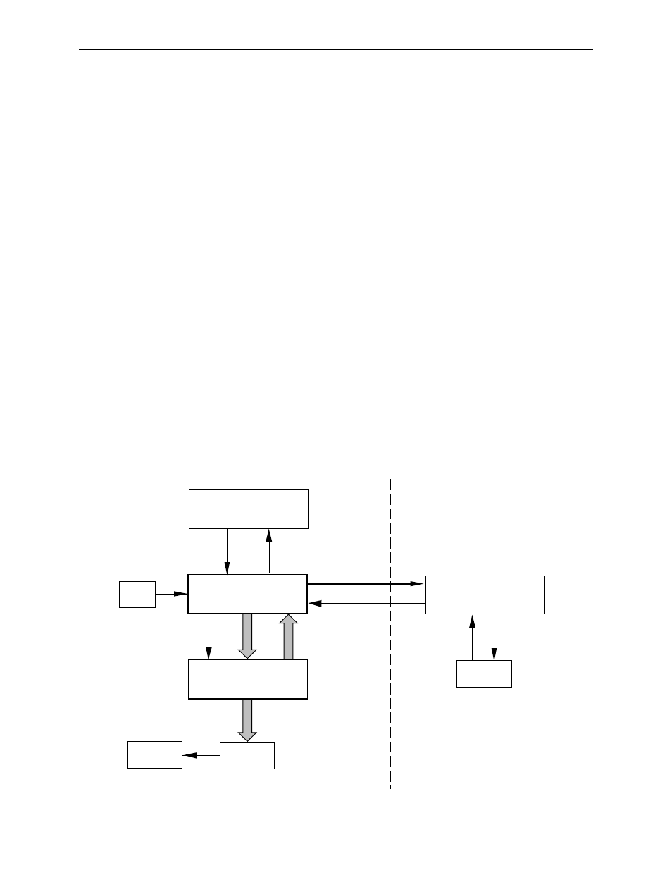
Panel Scanning
The Control Processor and the Control Panel MPU buses are linked by a
serial data connection. Refer to Figure 3-22.
1. At the beginning of each TV field, the I/O board sends a video sync
signal to the control panel MPU generating an interrupt.
2. The interrupt causes the MPU to scan the panel pushbuttons, controls,
and menus looking for changes that have occurred since the previous
interrupt. This scanning is done by sending signals though the I/O
board.
3. The MPU will analyze the collected data and send a message to the
frame control processor using the serial chips on the I/O board.
4. The frame control processor analyses the switcher state based on the
message from the MPU. The frame control processor will determine
what action is needed to update the switcher lights, buttons, or menu
text and sends a message to the MPU.
5. The MPU analyses the message from the frame control processor and
identifies which addresses need to be modified to complete the
switcher change.
6. The MPU sends a message to the I/O board to update the switcher
state, which will turn the various lamps and displays on or off.
Figure 3-22. Panel Keyboard Scanning.
Control Panel MPU
(064926)
Display
Driver
Menu
Display
Frame
Control Processor
Switcher
Status
Video
Sync
I/O Module
(064919)
Control Panel
Modules
Contol Panel
Electronics Frame
TP0715-01