Comm port loopback test, Comm port loopback test -19, Figure 5-13 – Grass Valley 1200 Installation User Manual
Page 151: Comm port loopback test menu -19, Figure 5-14, Loopback connector -19, Caution, Menu diagnostics comm port loopback test, Selecting
5-19
Menu Diagnostics
Comm Port Loopback Test
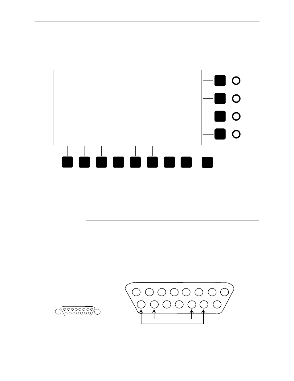
Selecting
[H - comm port loopback test]
from the Diagnostic menu will cause
the screen to appear as in Figure 5-13.
Figure 5-13. Comm Port Loopback Test Menu
CAUTION
The Comm Port Loopback test requires special equipment and trained personnel
to operate the test properly. Damage to the equipment is possible if the test is run
incorrectly.
Using a loopback connector (see Figure 5-14), data is sent out the COM
ports on the I/O board and monitored to see if the data is returned.
The purpose of this test is to verify that the comm path on the control panel
to the frame is operating correctly.
To stop the test, press any key on the keyboard.
Figure 5-14. Loopback Connector
Exit
GVG Model 1200 Panel version xxxxxx - 00A1
Copyright 1994, Grass Valley Group, Inc.
Select a diagnostic:
A - displays test
B - knob test
C - leverarm and joystick test
D - button/lamp DIM test
E - button/lamp BRIGHT test
F - walking lamp test
G - discrete LED test
H - comm port loopback test
Return rotary switch to position 0 to exit diagnostics and
return to DOS. At the DOS prompt, use '1200' to restart
Enter letter to select test: H
This test isn't implemented yet.
Press any key to return to menu . . .
J1
SERIAL COMM
TO VIDEO
ELECTRONICS FRAME
1
2
3
4
5
6
7
8
9
10
11
12
13
14
15
Male Connection on
Back of Control Panel
TX1
RX1
RX1
TX1
Female 15 pin D Loopback Connector
(Wiring Side)