Ac power connection and system powerup, Ac power connection and system powerup -16, Figure 2-8 – Grass Valley 1200 Installation User Manual
Page 44: Model 1200 connector pinouts -15, Figure 2-9, Ac line in connector j39 -16, Warning
2-16
Section 2 Ñ Installation
Figure 2-8. Model 1200 Connector Pinouts
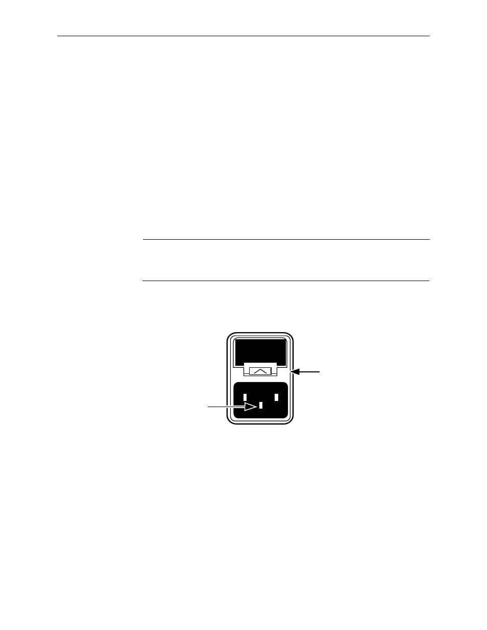
AC Power Connection and System Powerup
1. Plug the switcher frame power cord into the back of the Model 1200
frame at AC LINE IN connector J39 (Figure 2-9). Connect the other end
of the cord to an AC power source between 100 and 240 volts, 50Ð60 Hz.
2. Connect the control panel power cord to an AC power source.
Determine whether the power source is either within 90-135 Vac or 180-
265 Vac and set the manual switch located by the control panel plug to
the proper setting. Connect the other end of the cord into the back of the
Model 1200 control panel.
WARNING
To prevent danger of electric shock, ensure that the power
connector center conductor connects to a proper earth ground.
Figure 2-9. AC LINE IN Connector J39
3. Verify that all cabling is clear of cooling fans and that there are no loose
tools or other metal objects near power supply buses or connections.
4. Check that all Modules and Interconnect Adapters are seated firmly in
the frame.
5. Verify that the Control Panel and Signal Processor Frame AC power
cords are properly connected.
AC LINE IN
J39
100-240V 50-60HZ
5A FUSE
& SPARE
(AUTO-RANGING)
Fuse Compartment Latch
Pull up and out to check fuse
WARNING!
Earth Ground Conductor
Connect to a proper
earth ground to prevent
danger of electric shock