Sync pulse submodule, Sync pulse submodule -13, Figure 3-3 – Grass Valley 1200 Installation User Manual
Page 87: Frame modules, Generates the timing clocks for the other modules, Generates sync for the other modules, Figure 3-3. sync pulse submodule
3-13
Frame Modules
Sync Pulse Submodule
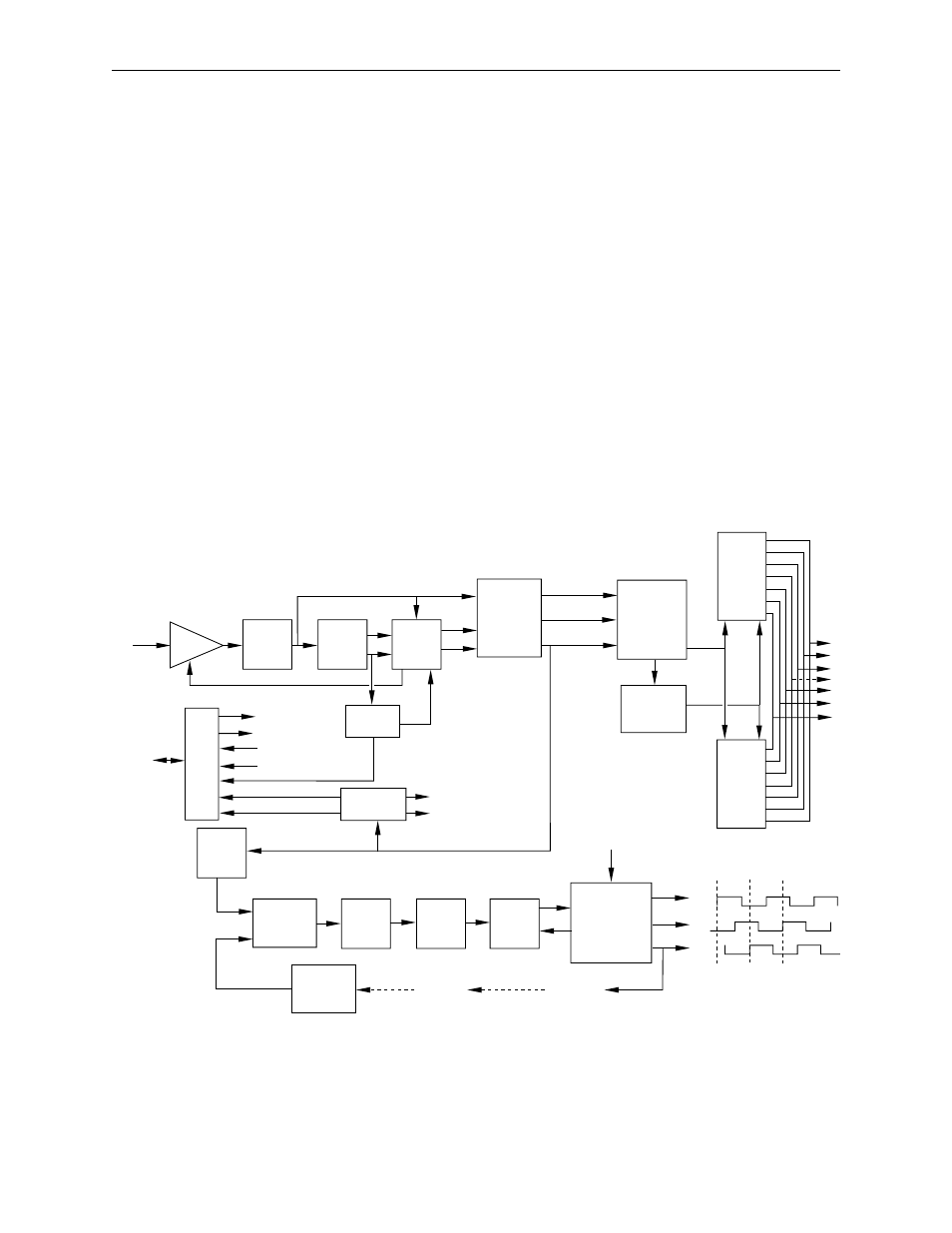
The Sync Pulse Generator Submodule (Figure 3-3) does the following:
■
Determines the television standard of the reference input (525, 625)
■
Automatically switches the Model 1200 to the correct standard
■
Has the system clock which is locked to the input reference
■
Generates the timing clocks for the other modules
■
Generates sync for the other modules
■
Has the system delay adjust
There are two main circuits on the Sync Pulse Generator Module, one for
creating sync signals from the reference video and one for generating
clocks from a phase-locked oscillator. H sync from the sync generator
circuit is compared to an H sync created by counting down the clock. The
phase difference between these two signals is used to adjust the clock
frequency so that the clock remains locked to the input reference.
Figure 3-3. Sync Pulse Submodule
BUFFER
LOW
PASS
FILTER
CLAMP
PULSE
GEN
SAMPLE
AND
HOLD
50%
PICKOFF
AND
SYNC
STRIPPER
SPG
RESET
GENERATOR
13.5 MHz
SPG
18 MHz
SPG
VARIABLE
DELAY
CPU
I/F
STANDARD
ID
H SYNC
SEP
TRI -STATE
PHASE
DETECTOR
ERROR
AMP
4.5
MHZ
VCO
CLOCK
MULTI
CLOCK
DIVIDER
AND
TRI-PHASE
GENERATOR
RX
BD
CLOCK
DIVIDER
TO
CONTROL
MODULE
FROM
CONTROL
MODULE
Reference
CPU
DC Offset Feedback
Low Passed Reference
Video Present
Sync
Tip
Back
Porch
50 / 60
16 X 9
Revision
Version
525 LED
625 LED
525
625
Vertical
Field ID
Comp Sync
TX
Ref Comp Sync
Field
ID
SPG
Reset
13.5 MHz
or
18 MHz
From CPU
VIDEO
PRESENT