Yaskawa VS-616PS5 Series Programming Manual User Manual
Page 19
VS-616PS5 Programming Manual
19
Control circuit terminal 14 accepts voltage signal:
Set terminal 14 signal selection (H3-08) to “0” for 0-10 VDC input signal or “1” for -
10 to 10 VDC input signal. The J1 jumper must also be cut to set-up terminal 14
to accept a voltage signal.
Notes:
1.
I value is reset to ”0” when operation stops.
2.
The upper limit of the I value can be set by parameter B5-04.
Increase the value of parameter B5-04 to upgrade control capability by
integration. If the control system is unstable and it cannot be stopped by
adjusting the integral time, output delay time, etc., decrease the set value
of parameter B5-04.
3.
PID control can be canceled by a multi-function contact input signal.
By setting any of parameters H1-01 to H1-06 to “19” and by closing the
contact during running PID control is disabled and the intended value sig-
nal itself is used as a frequency reference signal.
Setting Range:
0.00 to 25.00
Factory Default:
1.00
The proportional gain is the value by which the deviation signal is multiplied to gener-
ate a new frequency reference. Too high a setting will result in oscillations (instabil-
ity).
Too low a setting will result in a sluggish response.
B5-02 PID Control Proportional Gain
A
Intended
H3-06
(Deviation) -
+
P
1
2
B5-01
Value
Feedback
Calibration
Gain
Detected
Value
Offset
B5-01
B5-01
Output
Delay Time
Frequency
Reference
1 or 2
0
B5-06
B5-08
B5-07
B5-04
+
+
+
B5-03
B5-05
D
1
2
B5-05
D
+
+
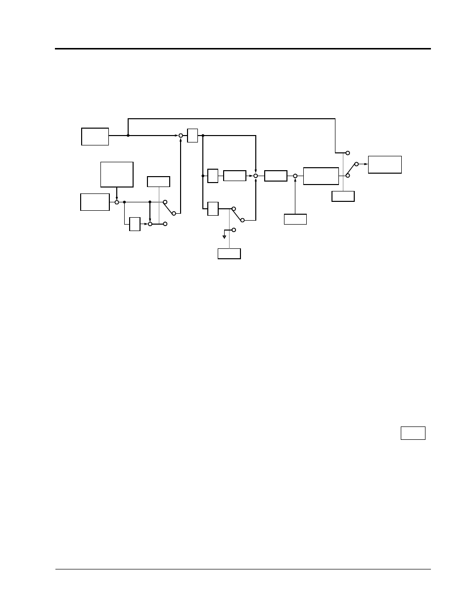
Figure 9 PID Control Block Diagram
B5-02
Limit
I
Limit
Section B: Application Parameters
B5 PID Control