Yaskawa VS-616PS5 Series Programming Manual User Manual
Page 63
VS-616PS5 Programming Manual
63
.
Notes:
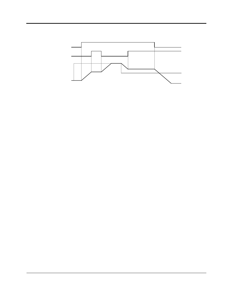
1. When both a hold reference memory selection (D4-01 = “1”) and an accel/
decel hold command are input, a stop command followed by a run command
will generate storage of the output frequency data until the accel/decel stop
command is released. Operation resumes after the frequency storage.
2. When the power supply is turned OFF after the accel/decel hold command is
input, the held output frequency is also stored.
3. When D4-01 is set to “0,” the held output frequency is not stored.
• Inverter Overheat OH2 Alarm (setting: “B”)
Inputting the inverter overheat alarm signal, “OH2” blinks on the digital operator dis-
play (Alarm condition only). The user can connect the dry contact of an external
heat sensor for indication of device over-temperature. To close an output contact
under this condition, set a multi-function contact output (H2-XX) to “20”.
• Multi-function Analog Input Enable/Disable (setting: “C”)
This setting allows terminal 16 multi-function analog input to be enabled (accepted)
or disabled (disregarded) via a digital input.
Open:
Terminal 16 command is not accepted.
Closed:
Terminal 16 command is accepted.
• Speed Control Integral Value Reset (setting: “E”)
This function allows the speed control integral value to be reset while the inverter is
running.
Open:
PI-control (adds the speed control integral values.)
Closed:
P-control (resets the speed control integral values by the integral time
constant).
OFF
ON
OFF
ON
ON
OFF
OFF
Fwd Run
Accel/Decel
Output
Hold Command
Frequency
Figure 32 Accel/Decel Hold Command Timing Diagram
Frequency
Reference
Section H: Control Circuit Terminal Parameters
H1 Digital Inputs