Yaskawa VS-616PS5 Series Programming Manual User Manual
Page 62
62
VS-616PS5 Programming Manual
Section H: Control Circuit Terminal Parameters
H1 Digital Intputs
• Local/Remote Selection (setting: “1”)
Selects the operation mode, only when the inverter is stopped.
Local:
Operation according to frequency reference and run command as
entered from digital operator.
Remote: Operation according to frequency reference and run command set by
B1-01 & B1-02, respectively.
Note: When local/remote selection is set by a multi-function contact input ter-
minal, local/remote selection from the digital operator key is disabled.
• Option/Inverter Selection (setting: “2”)
Selects whether operation is performed using a reference command from an option
card or from the inverter. Changeover is effective only when the inverter is stopped.
Open:
Runs by frequency reference and run command from inverter control
circuit terminal or digital operator (B1-01 & B1-02 dependant).
Closed:
Runs by frequency reference and run command from an option card.
• External Baseblock N.O. (setting: “8”)
Baseblock operation is performed when the contact input is closed. External base-
block operation differs, as described below, depending on the run command input
status.
Inputting an external baseblock signal while the inverter is running, causes a “BB”
indication on the digital operator display, and the inverter output is shut OFF.
After removing the external baseblock command, operation restarts at the previ-
ously referenced speed.
Inputting a stop signal along with an external baseblock signal while the inverter is
decelerating, causes” BB” to blink on the digital operator, the inverter output to shut
OFF, and the frequency reference to reset to 0.
• External Baseblock N.C. (setting: “9”)
Baseblock operation is performed similar to setting “8,” except that operation is per-
formed when the contact input is open.
• Accel/Decel Hold Command (setting: “A”)
The accel/decel hold command is used to temporarily hold the output speed at its
current level at the time the “Hold” command is applied. Upon entry of a stop com-
mand, the accel/decel hold condition releases and operation stops.
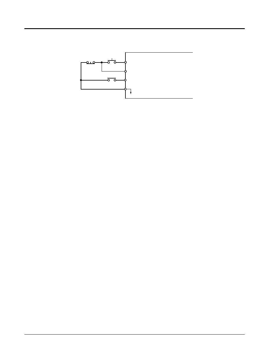
Figure 31 Terminal Function at 3-Wire Sequence Selection (H1-01 = “0”)
1
2
11
Run Command
(Run when “Closed”)
Stop Command
(Stop when “Open”)
FWD/REV Selection
(FWD when “Open”
REV when “Closed”)
5
Stop
Run