Yaskawa VS-616PS5 Series Programming Manual User Manual
Page 64
64
VS-616PS5 Programming Manual
Section H: Control Circuit Terminal Parameters
H1 Digital Inputs
• Up/Down Command (settings: Up = “10,” Down = “11”)
Allows the motor speed to be increased (Up command) or decreased (Down com-
mand) via contact closures. Requires the run command to be applied.
Notes:
1. Be sure to set Speed Reference Selection (B1-01) = “1.” When B1-01 = “0,”
Up/Down operation is disabled.
2. Upper limit speed = Maximum output speed (E1-06) × Speed Reference
Upper Limit (D2-01), if used.
3. The lower limit value is the larger of either the master Speed reference from
control circuit terminals 13 or 14, or the Speed Reference Lower Limit (D2-02).
4. With Hold Reference Memory Selection is enabled (D4-01 = “1”) and a hold
command input, the output frequency stored even after the power supply
turns OFF. When D4-01 = “0” the output frequency is not stored.
5. If the jog frequency reference is input during Up/Down operation, the jog fre-
quency reference has priority.
• Forward and Reverse JOG commands (settings: Fwd Jog = “12,” Rev Jog = “13”)
Enables forward and reverse run jog frequency commands.
UP command
Closed
Open
Open
Closed
DOWN command
Open
Closed
Open
Closed
Operation Status
Accel
Decel
Hold
Hold
Setting
Description
12
When closed-run forward at jog frequency reference (D1-09).
13
When closed-run reverse at jog frequency reference (D1-09).
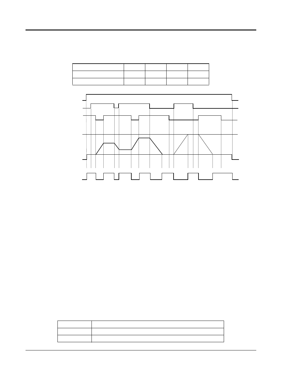
Figure 33 UP/DOWN Command Timing Diagram
FWD Run
UP Command S5
DOWN Command S6
Upper Limit Speed
Lower Limit Speed
Output Frequency
Frequency Agree Signal
D H U
U1
D1
D1
D
D
D
H
H
H
H
H
U
U
H
U:
Up (accelerating) status
D:
Down (decelerating) status
H:
Hold (constant speed) status
U1: Up status, with clamping at upper limit speed
D1: Down status, with clamping at lower limit speed