Yaskawa VS-616PS5 Series Programming Manual User Manual
Page 69
VS-616PS5 Programming Manual
69
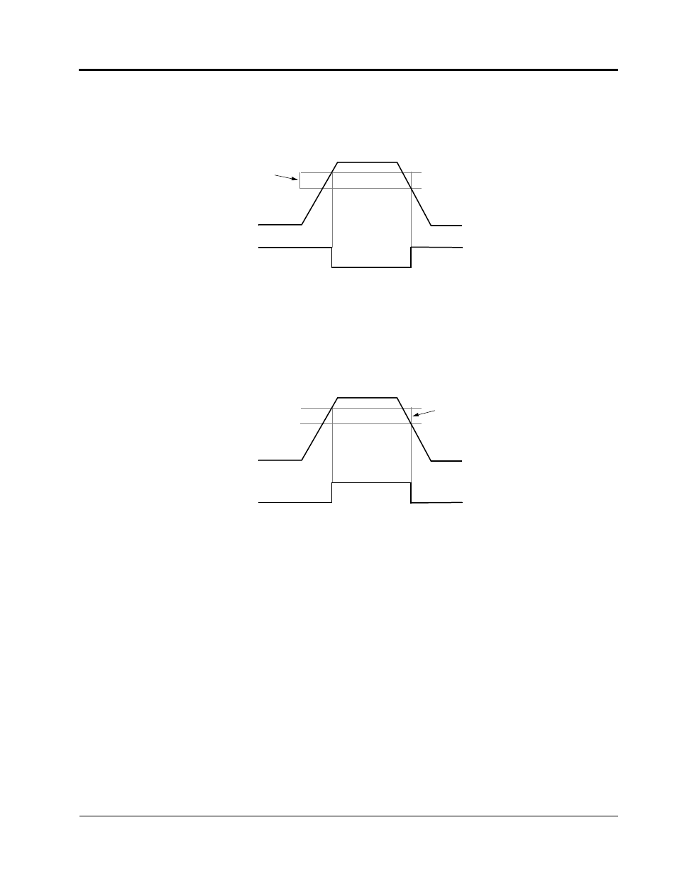
• Speed Detection 1 (setting: “4”)
Closes whenever the output speed is at or below the Speed Agree Detection Level
(L4-01). During acceleration from below the detection level, the output speed
increases through the Detection Bandwidth (L4-02) before the contact opens again.
This works in both forward and reverse operation.
• Speed Detection 2 (setting: “5”)
Closes whenever the output speed is at or above the Speed Agree Detection Level
(L4-01). During deceleration from above the detection level, the output Speed
decreases through the Detection Bandwidth (L4-02) before the contact opens
again. This works in both forward and reverse operation.
• Inverter Ready (setting: “6”)
Closes when the inverter is ready for operation (no faults or alarms).
• DC Bus Undervoltage (setting: “7”)
Closes when the main circuit DC bus voltage or control circuit power supply is drops
below the trip level, or when the main soft charge contactor (MC) is OPEN.
• Baseblock 1 - N.O. (setting: “8”)
Closes when the inverter output shuts OFF.
• Speed Reference Selection (setting: “9”)
Open when the speed reference is entered from the control circuit terminals or
option. Closes when the speed reference is input from the digital operator.
• Run Command Selection (setting: “A”)
Opens when run command is entered from the control circuit terminals or option.
Detection Width 1 (L4-02)
Output Speed
Speed
OFF
Detection Level 1 (L4-01)
Figure 39 Speed Detection 1 Signal Timing Diagram
Detection 1 Signal
ON
ON
Detection Width 1 (L4-02)
Output Speed
Speed
ON
Detection Level 1 (L4-01)
Figure 40 Speed Detection 2 Signal Timing Diagram
Detection 2 Signal
OFF
OFF
Section H: Control Circuit Terminal Parameters
H2 Digital Outputs