C.2 power supply wiring and grounding, A-15 – Yaskawa JAPMC-MC2303-E User Manual
Page 165
Appendix C FL-net System Grounding
C.2 Power Supply Wiring and Grounding
A-15
App
Appendices
C.2
Power Supply Wiring and Grounding
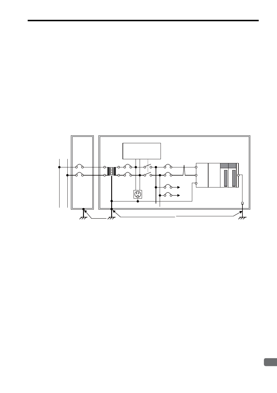
The following describes how to wire and ground an FL-net system power supply, and gives an example of power sup-
ply wiring and grounding in the distribution panel and controller panel as shown in Fig. C.3.
The power supply must be wired and grounded as follows:
• An insulating transformer with an electrostatic shield must be placed between the control power supply and
the controller power supply for insulation.
• The frames of the distribution and controller control panels must be grounded with a ground resistance of
100
Ω or less.
• The controller FG (frame ground) terminal must not be connected to the frame of the control panel but subject
to controller-dedicated grounding (ground resistance: 100
Ω or less).
• Wiring for a controller input power supply must be shortened as much as possible and a twisted cable must be
used for this purpose.
• The controller LG (line ground) terminal must be connected to a shielded terminal of the insulating trans-
former and grounded to the frame of the panel.
Fig. C.3 Example of Power Supply Wiring and Grounding in FL-net System
Relay circuit for
operation preparations
H
L
LG
FG
Control power
supply
Distribution
panel
Controller control panel
PLC, etc.
Panel ground (5.5 mm
2
or more)
Panel
ground
Controller ground (5.5 mm
2
or more)
AC100V
Ground of ground
resistance: 100
Ω or less
Ground of ground
resistance: 100
Ω or less
Ground of ground
resistance: 100
Ω or less