1 ethernet segment configuration example, 1 10base5 system, 2 10base-t system – Yaskawa JAPMC-MC2303-E User Manual
Page 69
5.1 Ethernet Segment Configuration Example
5.1.1 10BASE5 System
5-2
5.1 Ethernet Segment Configuration Example
FL-net (OPCN-2) is an FA control network that employs Ethernet as a communication medium (physical level, data
link) between FA controllers.
When the baud rate is 10 Mbps, the Ethernet physical layer supports five transmission methods: 10BASE5, 10BASE2,
10BASE-T, 10BASE-F, and 10BROAD36. When the baud rate is 100 Mbps, it supports four transmission methods:
100ASE-T2, 100BASE-T4, 100BASE-TX, and 100BASE-FX.
FL-net recommends the use of 10BASE5, 10BASE2, 10BASE-T, 100BASE-TX, and 100BASE-FX.
The following shows segment configuration examples for 10BASE5, 10BASE-T, and 100BASE-TX.
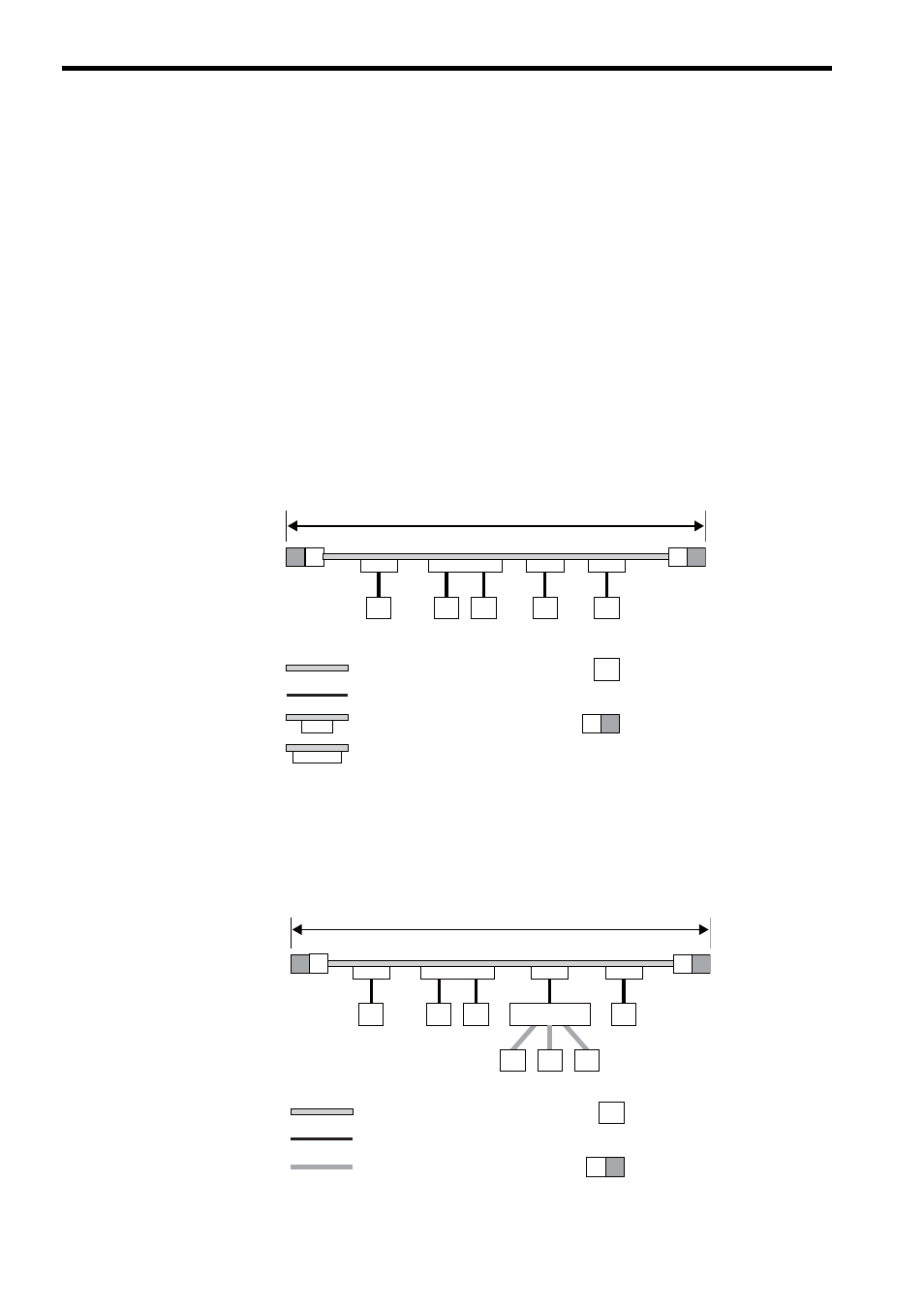
5.1.1 10BASE5 System
As shown in the following figure, the basic configuration consists of a 500-m (maximum length) coaxial cable and
nodes connected to the cable. This basic configuration is called a segment and one segment comprises a maximum of
100 nodes.
Each node is connected to the coaxial cable via a transceiver cable (AUI cable) and a transceiver.
There are two types of transceivers: a single-port transceiver that allows the connection of only one transceiver cable
(AUI cable) and a multi-port transceiver that allows the connection of multiple transceiver cables.
5.1.2 10BASE-T System
A hub (repeater hub) can be connected to a transceiver cable (AUI cable) to allow the connection of multiple nodes.
Use a twisted pair cable (10BASE-T) between the hub and node.
The maximum length between the hub and node is 100 m.
Segment (maximum length: 500 m)
N
N
N
N
N
N
㧦Coaxial cable
㧦Transceiver cable (AUI cable)
㧦Single-port transceiver
㧦Multi-port transceiver
㧦Node
㧦Terminator
N
N
N
Repeater hub
N
N
N
N
㧦Coaxial cable
㧦Transceiver cable (AUI cable)
㧦Twisted pair cable (10BASE-T)
N
Segment (maximum length: 500 m)
㧦Node
㧦Terminator