A-16 – Yaskawa JAPMC-MC2303-E User Manual
Page 166
Appendix C FL-net System Grounding
C.3 Network Equipment Connection in the FL-net System
A-16
C.3
Network Equipment Connection in the FL-net System
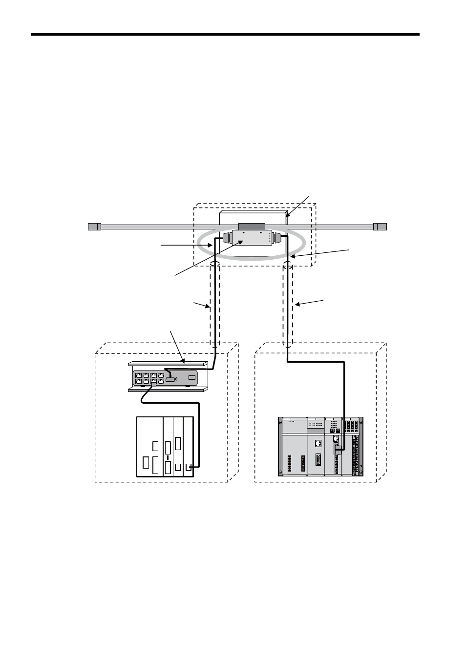
The following shows an example of installing network equipment (transceivers, hubs, etc.) in the FL-net system as
shown in Fig. C.4.
• Note that the transceiver should be installed in a metal installation box with a wooden insulation cover. The
installation box must be grounded with a ground resistance of 100
Ω or less.
• A transceiver cable must be wired to the control panel of the controller by means of a conduit. The conduit
must also be grounded with a ground resistance of 100
Ω or less.
• The hub must be installed within the control panel of the controller with a U-shaped fitting. The hub must be
electrically insulated from the fitting by rubber feet. The fitting must be grounded to the control panel of the
controller, and the control panel must be grounded with a ground resistance of 100
Ω or less.
Fig. C.4 Example of Network Equipment Connection in the FL-net System
Transceiver installation box
Transceiver insulating plate (wooden)
Transceiver cable
(AUI cable)
Transceiver cable
(AUI cable)
Conduit
Coaxial cable
Transceiver
U-shaped fitting for mounting hub
Hub
10BASE-T/100BASE-TX cable
Controller control panel
Controller control panel
Conduit
MP2300
218IF-02 262IF-01
SVB-01