Yaskawa JAPMC-MC2303-E User Manual
Page 61
4.2 FL-net Transmission Definition
4.2.2 Link Assignment Tab Page
4-8
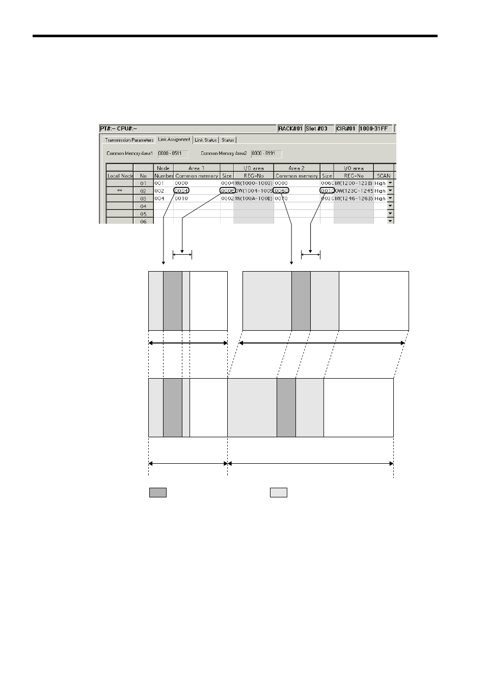
( 3 ) Link Assignment Setting Example and Common Memory Assignment Image
The following figure shows a link assignment example and a common memory assignment image.
Because areas 1 and 2 in the local node are used only for sending, they work as output registers (OW). Because areas 1
and 2 in other nodes are used only for reception, they work as input registers (IW).
Set by Transmission Parameters
Tab Page
0000
0004
00100012
051
1
IW1000OW1004 IW100A
IW100C
IW1200
OW123C
IW1246
IW1264
IW31FF
6 words
0000
0060
0100
0070
8191
Area 1
Area 2
10 words
㧦Local node (OW register)
㧦Other node (IW register)
FL-net common memory
(Set by Link Assignment
Tab Page)
Node number 1 (input)
Node number 1 (input)
Node number 2 (output)
Node number 2 (output)
Node number 4 (input)
Node number 1 (input)
Node number 2 (output)
Node number 4 (input)
Node number 1 (input)
Node number 2 (output)
Node number 4 (input)
Node number 4 (input)
Common memory area 1 size
(variable in a range from
0 to 200H)
Common memory area 2 size (variable in a range from 0 to 2200H)
(I/O ending register number
− common memory area 1 size)
CPU Module I/O register