4 parameter list for msg-snd function – Yaskawa JAPMC-MC2303-E User Manual
Page 94
6
Message Send and Receive Functions
6.1 Message Send Function
6.1.4 Parameter List for MSG-SND Function
6-9
6.1.4 Parameter List for MSG-SND Function
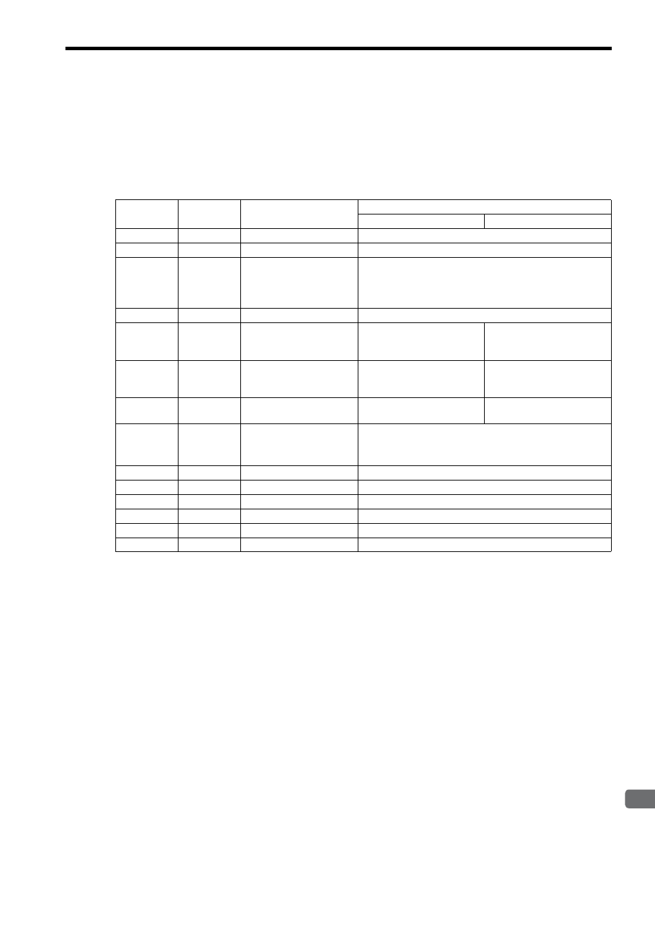
The Param input to the MSG-SND function is a parameter list structure consisting of 17 words. The value of the Param
input is the leading address (MA or DA) of the parameter list.
Use the parameter list to input the connection number, function code, and other related parameters. The processing
results and status are also output to the parameter list.
The parameter lists for the MEMOBUS and non-procedure communication protocols in FL-net are given below.
IN: Input, OUT: Output, SYS: Used by the system.
Refer to 6.1.5 Parameter Details for MSG-SND Function on page 6-10 for details on the parameters.
∗ Set the lower-place four bits of upper words of the remote station address when the remote station is another manu-
facturer’s product, and set the remote station CPU number when the remote station is Yaskawa CP series.
PARAM No.
IN/OUT
Contents
Description
Pro-Typ=1 (MEMOBUS)
Pro-Typ=2 (Non-procedure)
00
OUT
Processing result
The processing results are output here.
01
OUT
Status
The status of the current MSG-SND function is output here.
02
IN
Remote node number
Specifies the destination node number (1 to 254).
When the remote station number is set to 255, data is
sent to all nodes on the FL-net. However, this is valid
only for transparent message and log data clear.
03
IN
Option Not
used.
04
IN
Function code
09H: Word block read
0BH: Word block write
Others: Not used.
Setting not required.
05
IN
Data address
Specifies the FL-net virtual
address in the range of 0 to
65535.
Specifies the transaction code
as data leading address.
06
IN
Data size
Specifies the data size in the
range of 1 to 512 words.
Specifies the data size in the
range of 1 to 513 words.
07
IN
Remote CPU number
(address upper word)
Specifies the FL-net virtual address.
When the remote station is 262IF-01: 0
When the remote station is other than 262IF-01: 0 to 15
*
08
IN
Coil offset
Not used.
09
IN
Input relay offset
Not used.
10
IN
Input register offset
Not used.
11
IN
Holding register offset
Sets the offset word address of the holding registers.
12
SYS
Reserved by the system (1).
13 to 16
SYS
Reserved by the system (2).